Supercharge Your Innovation With Domain-Expert AI Agents!

Spring contact

A spring contact and compression spring technology, applied in the direction of clamping/spring connection, contact parts, etc., can solve the problems of large side pressure, height reduction and miniaturization of the conductive plug 101, and many factors of side pressure dispersion.

Inactive Publication Date: 2005-08-03
TE CONNECTIVITY GERMANY GMBH
View PDF0 Cites 0 Cited by
  • Summary
  • Abstract
  • Description
  • Claims
  • Application Information

AI Technical Summary

Problems solved by technology

[0006] 1. Because the soft middle part of the compression spring 103 is bent into a く shape, the side pressure acting on the conductive plug 101 is relatively large
[0007] 2. Since the lateral pressure acting on the conductive plug 101 is dispersed according to two factors: the bending position and the inclination direction of the bending portion of the compression spring 103, there are many factors causing the lateral pressure to disperse, and the lateral pressure is unstable
[0008] 3. In order to obtain the specified side pressure acting on the conductive plug 101, the inner diameter of the conductive tube 102 and the overall size of the conductive tube 102 must be increased relative to the shape of the compression spring 103, which cannot achieve height reduction and miniaturization

Method used


Image

  • Spring contact
  • Spring contact
  • Spring contact

Examples


Embodiment Construction

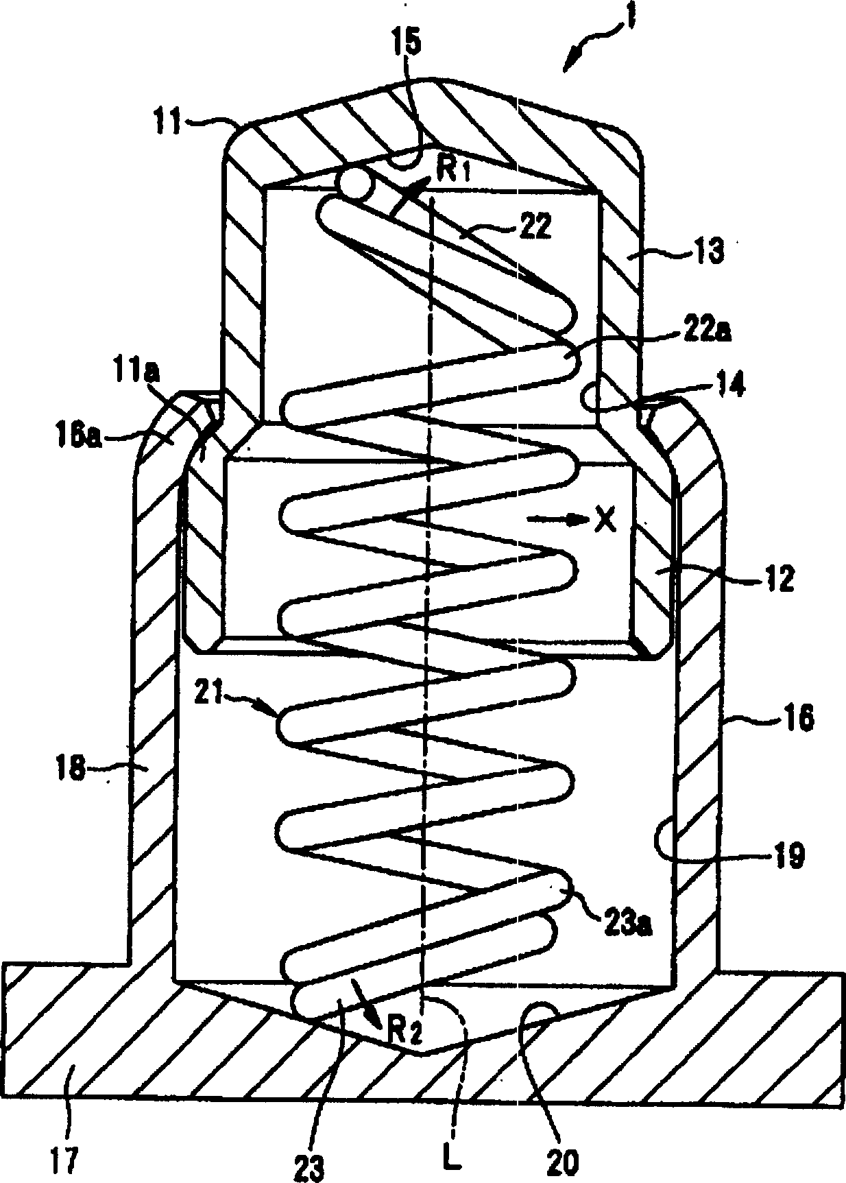
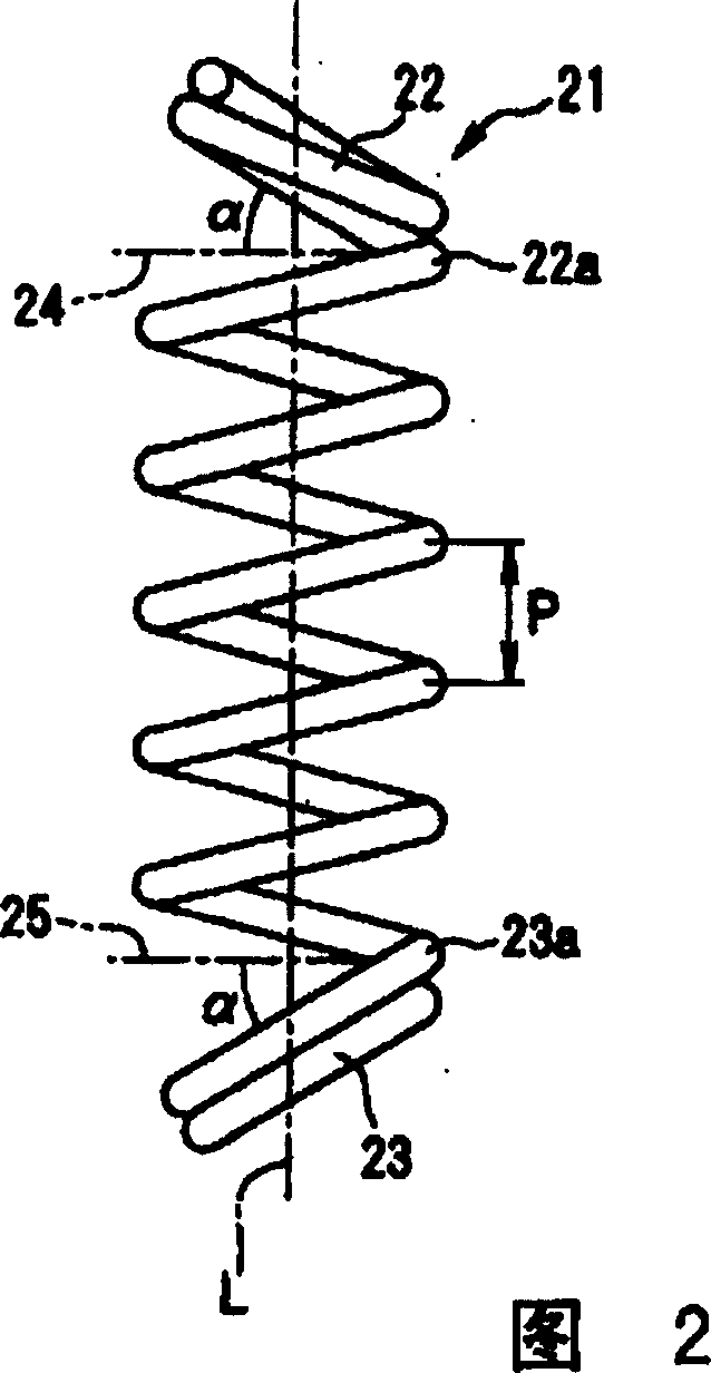
[0019] Embodiments of the present invention will be described below with reference to the accompanying drawings. figure 1 is a cross-sectional view of an embodiment of the spring contact of the present invention, but figure 1 The compression spring is not cut apart. Figure 2 is figure 1 Front view of the free state of the compression spring used in the spring contact shown.

[0020] figure 1 The shown spring contact 1 has a conductive plug 11 and a conductive tube 16, the conductive plug 11 is in contact with the built-in battery or antenna of the portable phone (not shown in the figure), the conductive tube 16 can freely slide to accommodate the conductive plug 11, and soldering onto the substrate (not shown in the figure). A compression spring 21 that presses the conductive plug 11 in a protruding direction is disposed inside the conductive tube 16 .

[0021] Here, the conductive tube 16 is composed of a soldering portion 17 and a cylindrical portion 18, and is made...


PUM


Abstract

The present invention provides a spring contact capable of stably and approximately evenly applying comparatively large side pressure to a conductive pin, and at the same time reducing the height and miniaturizing. This spring contact 1 comprises a conductive pin 11, a conductive tube 16, and a compression coil spring 21. The conductive tube 16 can slidably accommodating the conductive pin 11, and the compression coil spring 21 is mounted in the conductive tube 16 and pressing and energizing the conductive pin 11 in the projecting direction. At least one end of the end coils 22 and 23 of the compression coil spring 21 is inclined at a predetermined angle to a plane perpendicular to the center line L of the compression coil spring 21 and outwardly extended freely.

Description

technical field [0001] The present invention relates to a spring contact used for interconnection between a substrate and a built-in battery or between a substrate and an antenna in radio equipment such as a cellular phone. Background technique [0002] Previous such spring contacts, for example, were Image 6 The known type shown (see Utility Model No. 2529084). [0003] Such spring contacts 100 as Image 6 As shown in (A), it is a conductive plug 101 that is in contact with an electrode (not shown in the figure) such as a built-in battery, and the conductive plug 101 can be freely slidably accommodated and electrically connected to the conductive plug 101 on the substrate (not shown in the figure). The tube 102 is composed of a compression spring 103 that presses the conductive plug 101 arranged in the conductive tube 102 in the protruding direction. Both ends of the compression spring 103 are inserted into a hole 101 a formed in the conductive plug 101 and a hole 102 a f...

Claims


Application Information

Patent Timeline
IPC IPC(8): H01R13/24H01R4/48
Inventor 田中薰大津明彦
Owner TE CONNECTIVITY GERMANY GMBH
Features
  • R&D
  • Intellectual Property
  • Life Sciences
  • Materials
  • Tech Scout
  • Unparalleled Data Quality
  • Higher Quality Content
  • 60% Fewer Hallucinations
Learn More