Unlock instant, AI-driven research and patent intelligence for your innovation.

Level shifter and level shifter circuit

A mover and drive circuit technology, applied in the direction of logic circuit, voltage/current interference elimination, logic circuit connection/interface layout, etc.

Inactive Publication Date: 2005-09-07
III HLDG 6
View PDF1 Cites 0 Cited by
  • Summary
  • Abstract
  • Description
  • Claims
  • Application Information

AI Technical Summary

Problems solved by technology

However, the output transistors P2 and N2 are hard driven to each corresponding rail voltage V+ and V-, causing substantial electromagnetic emissions (EME) on every transition of the bus state

Method used


Image

  • Level shifter and level shifter circuit
  • Level shifter and level shifter circuit
  • Level shifter and level shifter circuit

Examples


Embodiment Construction

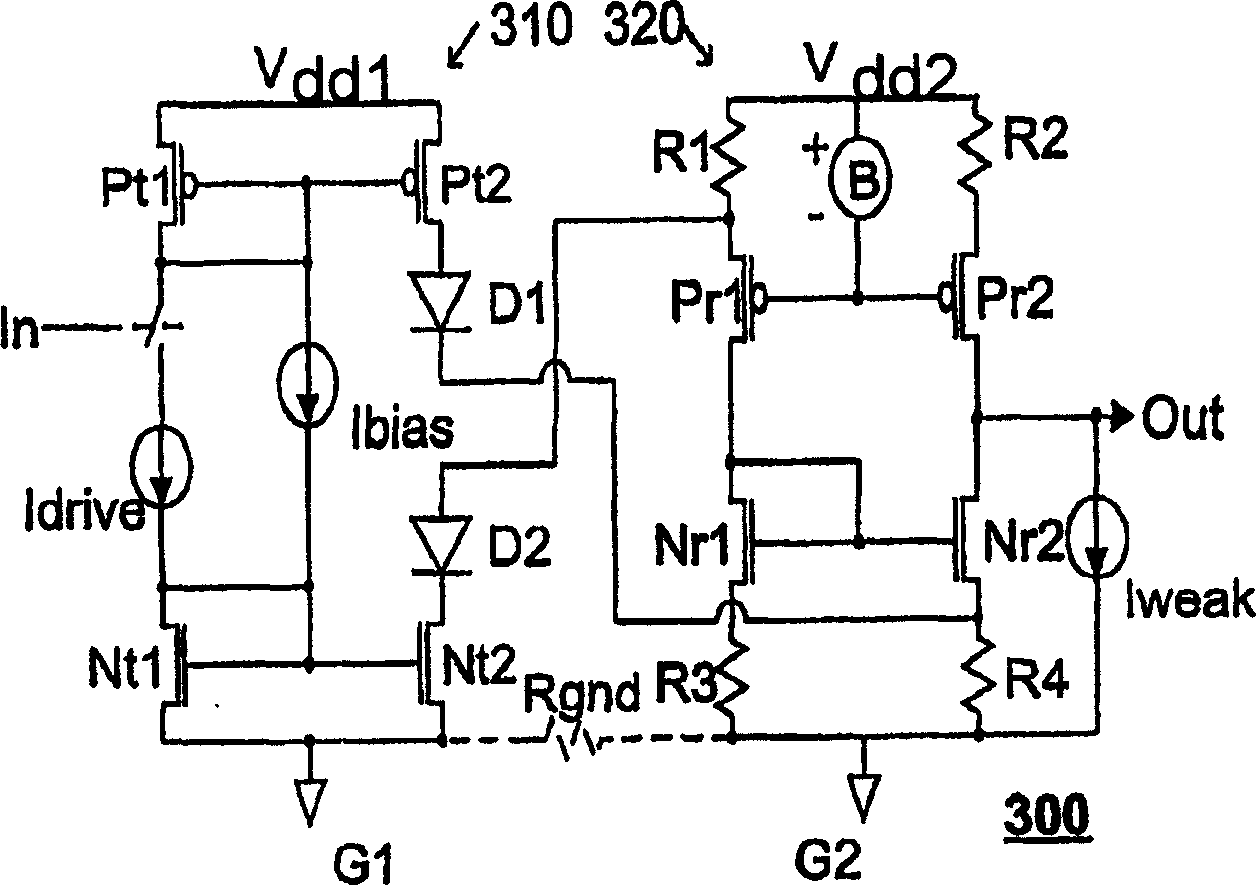
[0044] For convenience, the level shifter 300 referred to hereinafter includes a transmitting (driving) part 310 and a receiving (driven) part 320 . To make this technical term consistent with the prior art, the level shifter 300 may also be referred to as a transceiver. The transmitting part 310 is configured to operate with power supply potentials Vdd1 and G1, and the receiving part is configured to operate with power supply potentials Vdd2 and G2. These two groups of power supply potentials are basically independent, and the relationship between them is represented by a virtual resistance Rgnd between ground potentials G1 and G2. Note that as used here, the term ground potential is used only to denote a potential that a particular system uses as a reference potential, which may or may not be tied to ground potential, and may actually float with respect to other reference potentials.

[0045] The emission section 310 includes transistors Pt1, Pt2, Nt1 and Nt2 configured in ...


PUM


Abstract

A driving circuit provides a symmetric differential driving signal relative to one set of voltage potentials to a driver circuit that drives an output node to another set of voltage potentials. The differential driving signals from the driving system are equal and opposite to each other, thereby avoiding stray current flow between the driving system and the driven current mirrors. The transistors that provide the driving signal are continuously biased, using a weak bias in one logic state and stronger bias in the other state, to avoid hard-switching transients.

Description

technical field [0001] The present invention relates to the field of electronic circuits, and more particularly to a level shifter with independent ground potential and reduced electromagnetic emissions (EME). Background technique [0002] Level shifters are commonly used to provide communication of signals from one system having a first voltage potential range to another system having a different voltage potential range. For example, level shifters are commonly used in automotive applications because typical automotive systems operate on 0-18 volts, while typical integrated circuits typically operate on 0-3 volts, or 0-5 volts. A 3 or 5 volt output from an integrated circuit asserted as a "logic high" is not strong enough to be interpreted as a logic high in a 12 volt system. Level shifters provide proper mapping of voltage levels from one system to another to ensure correct communication of logic values. [0003] Figure 1 illustrates the principle of a conventional level...

Claims


Application Information

Patent Timeline
IPC IPC(8): H03K19/003H03K19/0185
CPCH03K19/018521H03K19/00361
Inventor B·辛格K·-J·德兰根M·布里狄斯
Owner III HLDG 6
Features
  • R&D
  • Intellectual Property
  • Life Sciences
  • Materials
  • Tech Scout
  • Unparalleled Data Quality
  • Higher Quality Content
  • 60% Fewer Hallucinations
Learn More