Supercharge Your Innovation With Domain-Expert AI Agents!

Reproducing device

A playback device and playback technology, which are applied in the fields of recording/reproducing by optical methods, instruments, and recording signal processing, etc., can solve the problems of complexity, inability to adapt to high speed, and long convergence time.

Inactive Publication Date: 2006-01-04
JVC KENWOOD CORP
View PDF2 Cites 0 Cited by
  • Summary
  • Abstract
  • Description
  • Claims
  • Application Information

AI Technical Summary

Problems solved by technology

Therefore, when a reproduction signal is input with a reproduction characteristic different from that at the time of determining the branch coefficient, it cannot adapt to
[0010] Moreover, for the latter in the above-mentioned existing playback device, since the target value of the PR equalization performed by the playback device is multi-valued, careful threshold value comparison must be performed with the error rate determiner 609, and there are problems due to noise and distortion. difficult to determine
In this way, in a device (for example, playback devices such as CDs and DVDs) to which various signals are input, due to the nature of the signal to be reproduced, the run length and the PR characteristic after equalization are different, therefore, due to the control of the threshold It becomes complicated, and there is a possibility that the convergence time before reaching a stable waveform equalization becomes longer
[0011] Moreover, in the conventional playback device, the system clock must be higher than the data rate, and cannot adapt to high-speed

Method used


Image

  • Reproducing device
  • Reproducing device
  • Reproducing device

Examples


Embodiment Construction

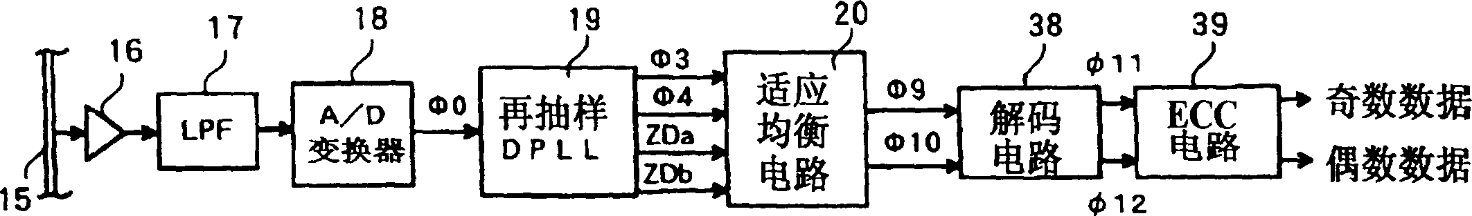
[0077] Below and attached Figure 1 Let us describe the embodiments of the present invention. figure 1 It is a block diagram of the first embodiment of the reproducing apparatus according to the present invention. In this figure, the run-length-limited code (digital signal) photoelectrically converted and amplified by the PD head amplifier 16 from the optical disc 15 on which the run-length-limited code is recorded at high density is blocked by a low-pass filter (LPF) 17. The frequency (noise) component is then supplied to the resampling DPLL 19 through the A / D converter 18, and an AGC circuit (not shown) performs automatic gain control (AGC) as necessary to make the amplitude constant. Also, the position where the A / D converter is set may be any position before the resampling DPLL 19.

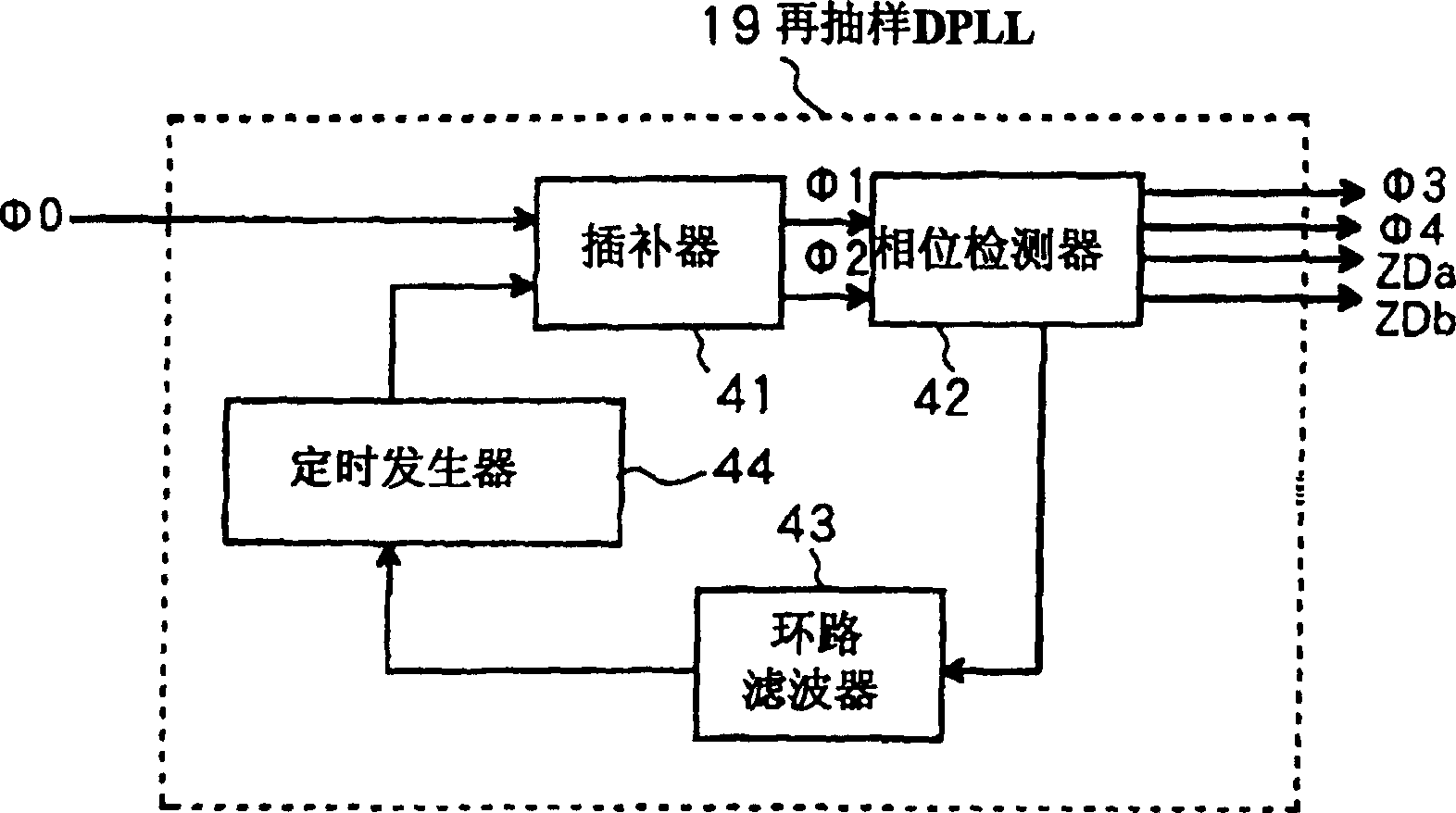
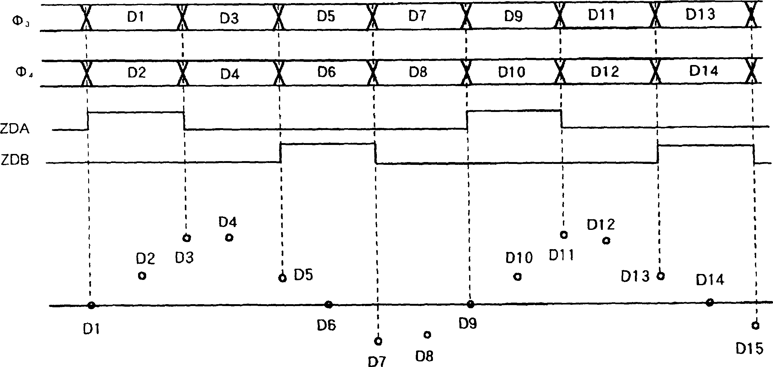
[0078] The resampling DPLL 19 generates such digital data (i.e., the resampled data in which the phase of the digital data is 0°, 180°, and 180°): with a digital PLL circuit that completes ...


PUM


Abstract

A signal of a run-length-limited code is reproduced from a recording medium. The reproduced signal is sampled to generate a sampling-resultant signal. An odd-sample signal and an even-sample signal are generated in response to the sampling-resultant signal. A first transversal filter subjects the odd-sample signal to first partial-response waveform equalization to generate an equalization-resultant odd-sample signal. The first partial-response waveform equalization depends on first tap coefficients. The first tap coefficients are controlled on a feedback basis to minimize an error of the equalization-resultant odd-sample signal. A second transversal filter subjects the even-sample signal to second partial-response waveform equalization to generate an equalization-resultant even-sample signal. The second partial-response waveform equalization depends on second tap coefficients. The second tap coefficients are controlled on a feedback basis to minimize an error of the equalization-resultant even-sample signal. The equalization-resultant odd-sample signal is decoded. The equalization-resultant even-sample signal is decoded.

Description

technical field [0001] The present invention relates to a playback apparatus, and more particularly, to a playback apparatus for playback from a recording medium such as an optical disc, and a playback apparatus including a waveform equalization circuit for performing waveform equalization on run-length-limited codes. Background technique [0002] In a reproducing apparatus that reproduces the run-length restricted code from a recording medium such as an optical disc on which the run-length restricted code is recorded at a high density, in order to remove the waveform distortion of the reproduced signal, a partial response (hereinafter referred to as PR) is used. A waveform equalization circuit with equalization characteristics is known in the prior art (Japanese Patent Laid-Open Publication No. 10-106161). [0003] Figure 37 A block diagram showing an example of the conventional playback apparatus. In this figure, the run-length-limited code reproduced from the optical di...

Claims


Application Information

Patent Timeline
Patent Type & Authority Patents(China)
IPC IPC(8): G11B20/10G11B7/00G11B7/005
CPCG11B20/10138G11B20/10083G11B20/10046G11B20/10009G11B20/10148G11B20/10092G11B20/10166G11B20/10111
Inventor 户波淳一郎
Owner JVC KENWOOD CORP
Features
  • R&D
  • Intellectual Property
  • Life Sciences
  • Materials
  • Tech Scout
  • Unparalleled Data Quality
  • Higher Quality Content
  • 60% Fewer Hallucinations
Learn More