
Eureka
For R&D, Eureka makes reading and utilizing patents & technical documents easy.
Eureka AIR
Designed for self-driven R&D workflows. Generate viable solutions, solve complex R&D challenges, empower your innovation with AI.

Eureka Materials
Designed for material experts only. Revolutionize your material R&D, from search, analyze, to developing new materials.

TechResearch
Generate reliable direction feasibility study reports for your R&D in just a few steps.

TechSeek
Discover and master advanced knowledge NOW. Basics, ideas, possibilities, all at once.

TechMind
As an expert in R&D Theories, TechMind can generates customized viable solutions instantly.

TechRisk
Analyze your overall solution with one click, know your potential R&D risks in advance.

TechMonitor
Get weekly tech updates, stay abreast of the latest tech innovations and key insights.
Fuel injection valve
A technology for fuel injection valves and internal combustion engines, applied in fuel injection devices, special fuel injection devices, charging systems, etc., can solve problems such as enlarging sealing problems, and achieve the effect of reliable sealing and simple cost
- Summary
- Abstract
- Description
- Claims
- Application Information
AI Technical Summary
Problems solved by technology
Method used
Image

Examples
Embodiment Construction
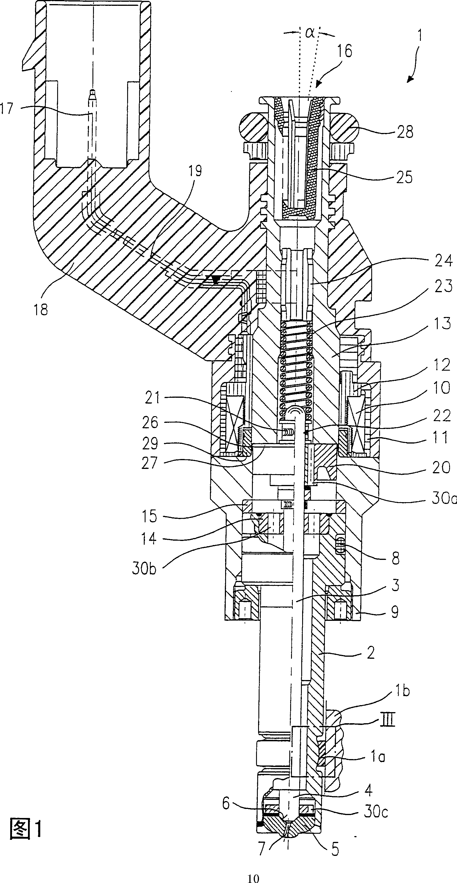
[0021] The fuel injection valve 1 according to the invention shown in FIG. 1 with a sealing ring 1 a is designed in the form of a fuel injection valve for a fuel injection system for a mixture-compressing, forced-ignition internal combustion engine. The fuel injector 1 is accommodated in a receiving bore, not shown in detail here, of a cylinder head 1b. The cylinder head 1b is shown as a cutaway plane only in the region of the sealing ring 1a, since this region which is relevant for the invention is described in more detail in the following figures. The fuel injector 1 is particularly suitable for injecting fuel directly into a combustion chamber (not shown) of an internal combustion engine.
[0022] The fuel injection valve 1 is formed by a nozzle body 2 in which a valve needle 3 is guided. The valve needle 3 is operatively connected to a valve closing body 4 which cooperates with a valve seat surface 6 arranged on a valve seat body 5 to form a sealing seat. In this exempla...
PUM
 Abstract
Description
Claims
Application Information
 - R&D Engineer
- R&D Manager
- IP Professional
- Industry Leading Data Capabilities
- Powerful AI technology
- Patent DNA Extraction
Browse by: Latest US Patents, China's latest patents, Technical Efficacy Thesaurus, Application Domain, Technology Topic, Popular Technical Reports.
© 2024 PatSnap. All rights reserved.Legal|Privacy policy|Modern Slavery Act Transparency Statement|Sitemap|About US| Contact US: help@patsnap.com