Light-shading wind guiding structure

A structure and shading technology, applied in optics, instruments, projection devices, etc., can solve problems such as affecting images, light leakage, and inability to shield light.

Inactive Publication Date: 2006-01-18
BENQ CORP
View PDF0 Cites 1 Cited by
  • Summary
  • Abstract
  • Description
  • Claims
  • Application Information

AI Technical Summary

Problems solved by technology

In this way, the blades are bound to be unable to completely shield the light leaked from the tuyeres.
In turn, there will be light leakage to the outside of the housing, affecting the output image

Method used


Image

  • Light-shading wind guiding structure
  • Light-shading wind guiding structure
  • Light-shading wind guiding structure

Examples


Embodiment Construction

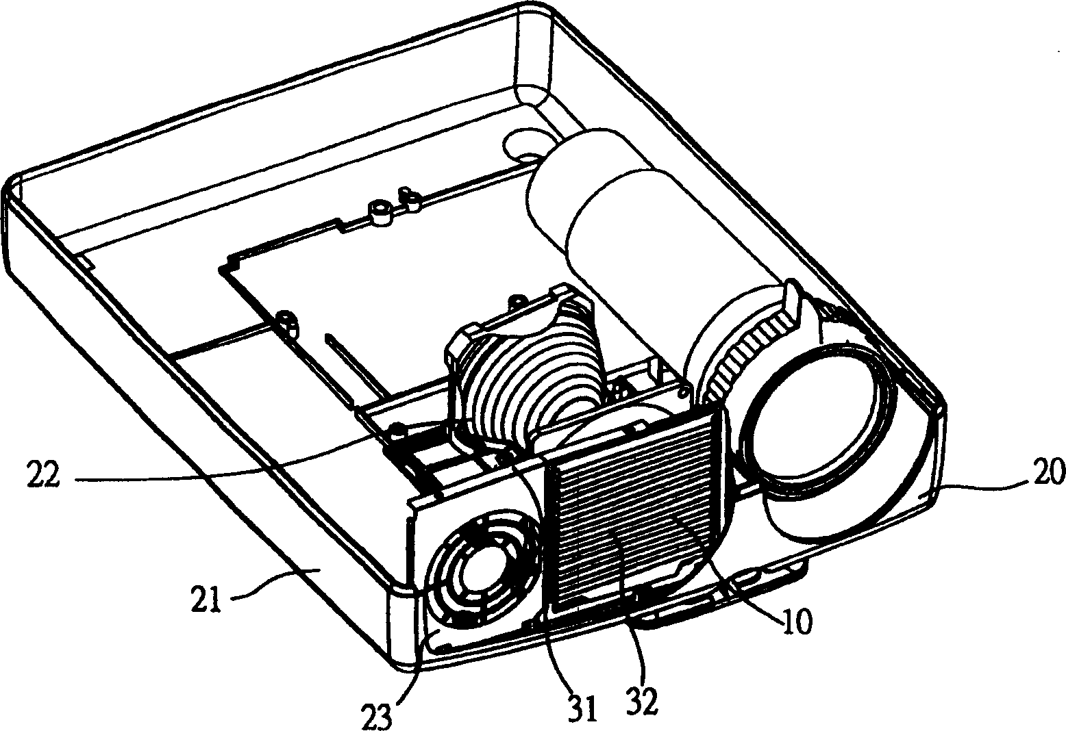
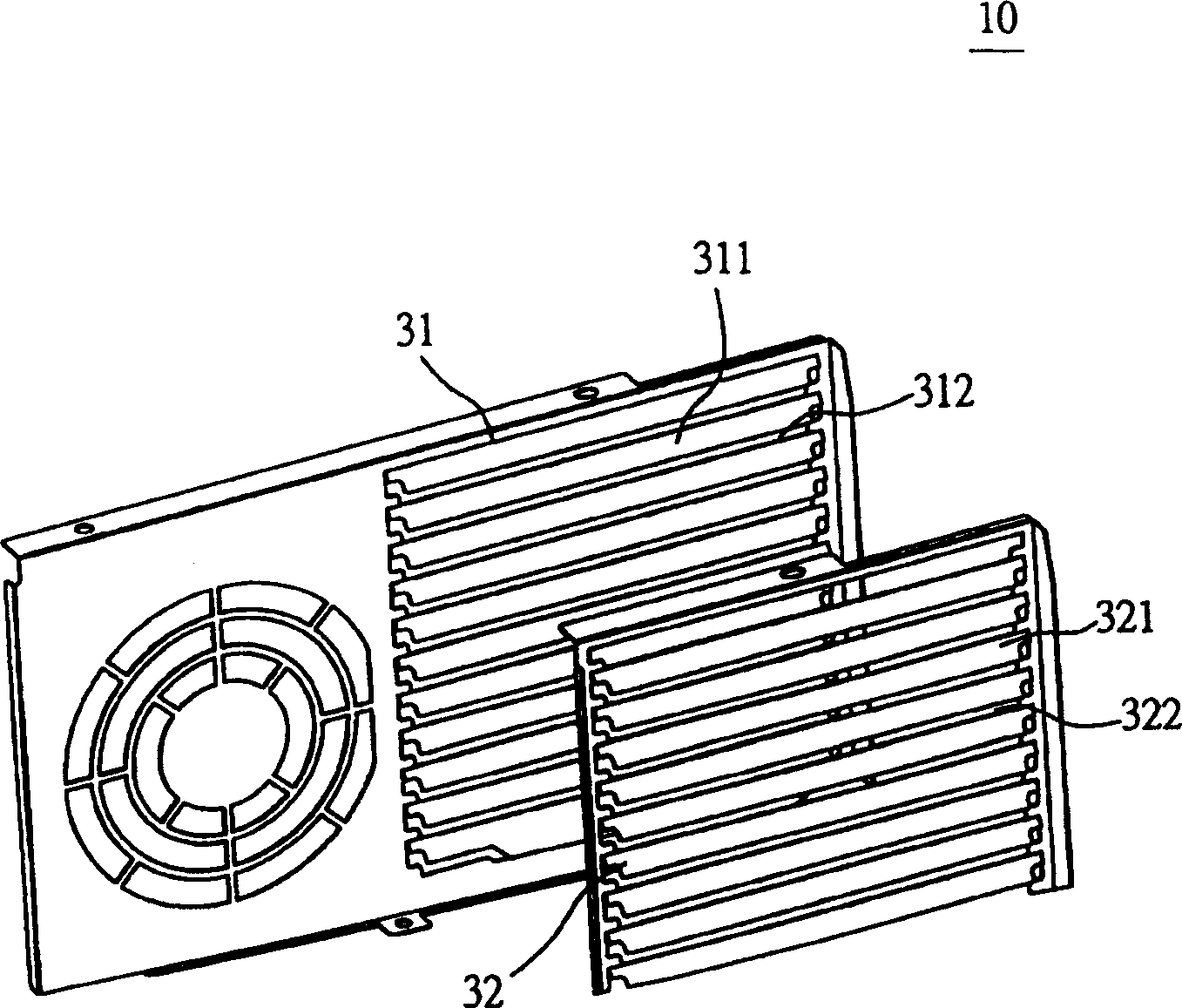
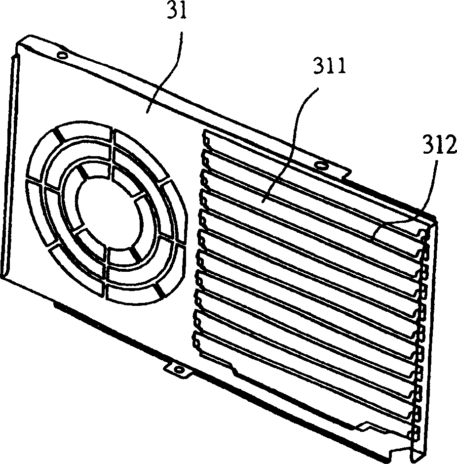
[0025] The present invention provides a light-shielding and wind-guiding structure 10 and an image output device 20 comprising the structure. However, the shading and wind guiding structure 10 of the present invention is not limited to be installed on the image output device 20 , and can also be installed on other devices.

[0026] see figure 1 , figure 1 It is a schematic diagram of an embodiment in which the shading and wind guiding structure 10 is applied to the image output device 20 . Such as figure 1 As shown, the shading and wind guiding structure 10 can be installed on the image output device 20 for heat dissipation and wind guiding. The image output device 20 has a housing 21 and a lamp 22 . The lamp 22 is installed in the casing 21 . The casing 21 has a vent 23 . As far as the embodiment is concerned, the image output device 20 may be a projector, a slide projector, a projector, and a device with a similar image output function. The light-shielding and wind-gu...


PUM


Abstract

The invention provides a shading wind transmitting structure and the image output equipment including the structure. The structure provides the function of cooling and transmitting the wind for the equipment and includes the first set and the second one, the first one installed in the shell of the equipment and corresponding to the air hole of the shell for screening the rays emitted by the air hole, part of the lights unscreened become the leaked rays, and the second one installed on the outer side of the first one for screening the leaked rays.

Description

technical field [0001] The present invention relates to a blowhole-cover structure, in particular to an image output device including the structure. Background technique [0002] The current trend of the world is constantly moving towards the era of multimedia, and sound and light effects are required in everything, and the image output device is an indispensable device in this trend. There are many different types of image output devices on the market, including single-shot projectors, three-shot projectors, slide projectors, projectors, and more. A common feature of such image output devices is that they generate high heat due to the internal light emitting devices. Therefore, heat dissipation has become a common problem of such image output devices. [0003] Generally speaking, this type of image output device is designed with a vent device for heat dissipation on the casing. However, light inside the case also leaks through the vents, which...

Claims


Application Information

Patent Timeline
Patent Type & Authority Patents(China)
IPC IPC(8): G03B21/16
Inventor 徐世龙林荧郁
Owner BENQ CORP
Why Eureka
Try Eureka