
Mounting structure of automatic chemical supply device

An automatic supply and chemical technology, used in piping systems, mechanical equipment, gas/liquid distribution and storage, etc., can solve the problem of inability to close the space around hoses and joints, leakage of chemical fumes, and musculoskeletal system diseases of staff and other problems, to achieve the effect of preventing musculoskeletal system diseases and improving work convenience

Active Publication Date: 2019-03-05
SUBARU TECNICA INTERNATIONAL
View PDF6 Cites 7 Cited by
  • Summary
  • Abstract
  • Description
  • Claims
  • Application Information

AI Technical Summary

Problems solved by technology

[0015] But according to this structure, to put the heavy chemical hoses and nitrogen hoses to the shelving part in the building, the staff must bend down to put the hoses to the shelving part, but this work will be difficult due to the weight of the hoses. Causes of musculoskeletal disorders in workers
[0016] Moreover, when transporting chemicals and nitrogen, chemical hoses and nitrogen hoses are connected to tank trucks and chemical storage tanks and nitrogen storage tanks, and there is a problem that chemical leak-proof screen doors cannot be installed
Moreover, even if a screen door is installed, the surrounding space where the hose is connected to the joint cannot be closed, leaving it exposed
Therefore, there is a problem that external pollutants such as dust, rainwater, and snow will flow into the device, and chemical fumes (Fume) generated in the device will also directly leak out.

Method used


Image

  • Mounting structure of automatic chemical supply device
  • Mounting structure of automatic chemical supply device
  • Mounting structure of automatic chemical supply device

Examples


Embodiment Construction

[0069] The automatic chemical supply device of the present invention will be described in detail below with reference to the accompanying drawings.

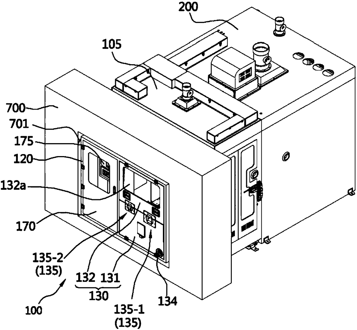
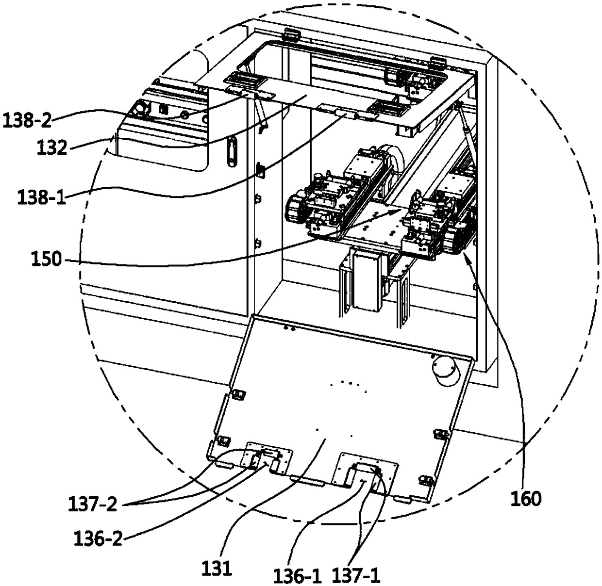
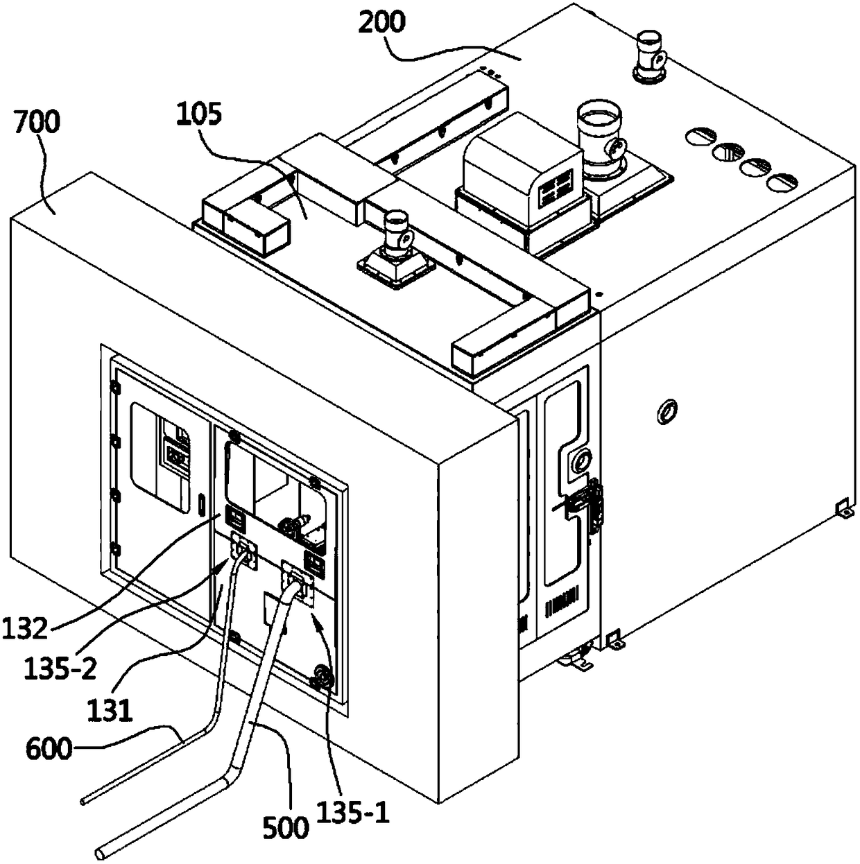
[0070] refer to Figure 1 to Figure 4 , the automatic chemical supply device 100 of the present invention is a chemical female joint 210 ( Figure 5 ) and the device for automatically connecting the chemical male connector 510 and the nitrogen male connector 610 on the nitrogen female connector (not shown), the chemical male connector 510 and the nitrogen male connector 610 are connected to the chemical tank (not shown) of the tank lorry (tank lorry) Shown) chemical hose 500 and nitrogen hose 600 ends.

[0071] When pointing the direction below, with the shield door 130 as a reference, the direction where the tanker and the operator are located is the rear, and the direction where the housing body 200 is located is the front.

[0072] The above-mentioned automatic chemical supply device 100 is composed of: a conveying part casi...


PUM


Abstract

The invention aims at providing a setting structure of an automatic chemical supply device. When an operator puts a hose on a putting part, the putting part is close to an operator to the greatest extent, and sickness of an operator can be prevented from being caused; the setting structure of the automatic chemical supply device comprises a building wall (700), and the automatic chemical supply device. The building wall is in through connection with an opening part inside and outside a building, the automatic chemical supply device comprises the putting part (150) and a conveying unit (160), the putting part (150) puts a chemical hose (500) from the chemical tank and used for chemicals, the conveying unit conveys the putting part (150) front and back, the chemical hose (500) is connected with a building inner chemical tank, and when a worker puts the chemical hose (500) on the putting part (150), the putting part (150) is located in inner space of the opening part 701.

Description

technical field [0001] The invention relates to an installation structure of an automatic chemical supply device. In more detail, the hose shelving part is arranged on the opening part of the wall, which improves the working convenience and prevents the operator from being injured. Background technique [0002] Generally, companies that manufacture semiconductors, semiconductor devices, LCDs, OLEDs, pharmaceutical companies, and paint companies that use hazardous chemicals use a variety of chemicals, and the methods of safely supplying these chemicals are also diversifying. [0003] This chemical is generally transported from the chemical tank of the tank truck (tank lorry) parked outside the building to the chemical storage tank (chemical storage tank) in the building, and then transported from the chemical storage tank to the unit engineering room. . [0004] The prior art method of delivering chemicals from the above tank trucks to the chemical storage tanks uses a metho...

Claims


Application Information

Patent Timeline
IPC IPC(8): F17D1/12F17D5/02
CPCF17D1/12F17D5/02
Inventor 尹炳春宋勇益金东炫金南荣
Owner SUBARU TECNICA INTERNATIONAL
Learn More