An electric field coupled wireless power transmission system

A wireless power transmission and coupling technology, applied in electrical components, circuit devices, etc., can solve problems such as transmission power reduction, transmission capacitance reduction, electric field electronic equipment interference, etc., to achieve the effect of improving safety

Active Publication Date: 2018-05-25
苏州卡方能源科技有限公司
View PDF8 Cites 0 Cited by
  • Summary
  • Abstract
  • Description
  • Claims
  • Application Information

AI Technical Summary

Problems solved by technology

But this system requires higher voltages (kilovolts) to generate an electric field of sufficient strength to transmit energy, and safety becomes an issue
At the same time, since two sets of polar plates are generally used in parallel, the transmission capacitance of the entire system is further reduced, resulting in a reduction in transmission power.
Leaked electric fields can also interfere with surrounding electronic equipment

Method used


Image

  • An electric field coupled wireless power transmission system
  • An electric field coupled wireless power transmission system
  • An electric field coupled wireless power transmission system

Examples


Embodiment 1

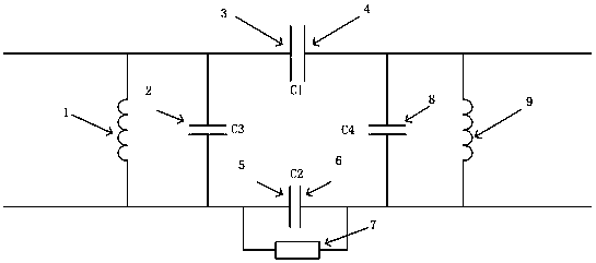
[0045] Embodiment 1: as Figure 1-2 As shown, an electric field coupled wireless power transmission system includes a pre-stage circuit part, a post-stage circuit part, and an electrode plate part;

[0046] The pre-stage circuit part is connected to the mains power grid part, and the pre-stage circuit part is mainly composed of a filter circuit, a power factor correction circuit, a power frequency rectification circuit, a high-frequency AC inverter circuit and a compensation network; the pre-stage circuit part is connected to In the power grid, the current is filtered, rectified, and inverted to generate high-frequency high-voltage voltage, which is supplied to the emitter plate, and the emitter plate includes the emitter plate P S1 (3), emitter plate P S2 (5), the emitter plate is used to excite high-frequency alternating electric field;

[0047] The latter part of the circuit is connected to the electrical part, and the latter part is mainly composed of a compensation netw...

Embodiment 2

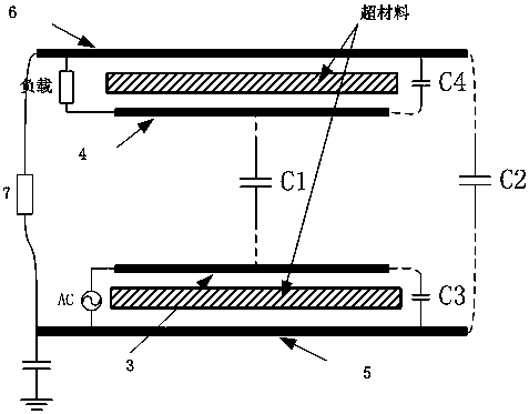
[0056] Embodiment 2: as figure 1 , image 3 As shown, an electric field coupled wireless power transmission system includes a pre-stage circuit part, a post-stage circuit part, and an electrode plate part;

[0057] The pre-stage circuit part is connected to the mains power grid part, and the pre-stage circuit part is mainly composed of a filter circuit, a power factor correction circuit, a power frequency rectifier circuit, a high-frequency AC inverter circuit and a compensation network; the pre-stage circuit part is connected to In the power grid, the current is filtered, rectified, and inverted to generate high-frequency high-voltage voltage, which is supplied to the emitter plate, and the emitter plate includes the emitter plate P S1 (3), emitter plate P S2 (5), the emitter plate is used to excite high-frequency alternating electric field;

[0058] The latter part of the circuit is connected to the electrical part, and the latter part is mainly composed of a compensatio...

Embodiment 3

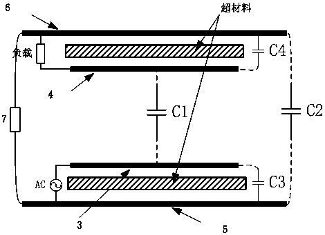
[0065] Embodiment 3: as figure 1 , figure 2 , Figure 4 As shown, an electric field coupled wireless power transmission system includes a pre-stage circuit part, a post-stage circuit part, and an electrode plate part;

[0066] The pre-stage circuit part is connected to the mains power grid part, and the pre-stage circuit part is mainly composed of a filter circuit, a power factor correction circuit, a power frequency rectification circuit, a high-frequency AC inverter circuit and a compensation network; the pre-stage circuit part is connected to In the power grid, the current is filtered, rectified, and inverted to generate high-frequency high-voltage voltage, which is supplied to the emitter plate, and the emitter plate includes the emitter plate P S1 (3), emitter plate P S2 (5), the emitter plate is used to excite high-frequency alternating electric field;

[0067] The latter part of the circuit is connected to the electrical part, and the latter part is mainly compose...


PUM


Abstract

The invention relates to an electric field coupled wireless power transmission system, which belongs to the technical field of wireless power transmission. Including the pre-stage circuit part, the post-stage circuit part, and the electrode plate part; the pre-stage circuit part is connected to the mains grid part, and the pre-stage circuit part is mainly composed of a filter circuit, a power factor correction circuit, a power frequency rectifier circuit, and a high-frequency AC inverter. circuit and compensation network; the front-stage circuit part is connected to the power grid, and the current is filtered, rectified, and inverted to generate high-frequency high-voltage voltage, which is supplied to the emitter plate; the post-stage circuit part is mainly composed of compensation network and rectifier circuit; receiving The plate is located in the electric field excited by the emitter plate and induces a high-frequency alternating voltage of the same frequency. The high-frequency alternating voltage is rectified by the rectifier circuit after the compensation network and then outputs a DC voltage; the electrode plate is partially connected to the previous circuit and between subsequent circuits. The invention greatly improves the safety of the system, transmits power, and can reduce energy dissipation and electromagnetic interference at the same time.

Description

technical field [0001] The invention relates to an electric field coupled wireless power transmission system, which belongs to the technical field of wireless power transmission. Background technique [0002] As early as 1897, Nikola Tesla proposed the concept of wireless power transmission and registered more than 20 invention patents. A wireless power transmission system that can transmit 60 watts of power at a distance of 2 meters. This has aroused the interest and enthusiasm of the majority of scientists. [0003] Wireless power transmission technology has made great progress since then, but most systems are based on the principle of magnetic induction or magnetic resonance coupling. Both systems generate an alternating magnetic field at the transmitting end and induce an induced current at the receiving end by the principle of electromagnetic induction to complete the wireless transmission of energy. [0004] However, both magnetic induction and magnetic coupling res...

Claims


Application Information

Patent Timeline
Patent Type & Authority Patents(China)
IPC IPC(8): H02J50/12
Inventor 李思奇竹立岩
Owner 苏州卡方能源科技有限公司
Why Eureka
Try Eureka