Phase-locked loop circuit of eliminating self-shaking in signals received by control circuit

A technology for controlling circuits and signals, applied in the field of self-jitter, and can solve problems such as data loss

Inactive Publication Date: 2006-01-18
INTEL CORP
View PDF0 Cites 0 Cited by
  • Summary
  • Abstract
  • Description
  • Claims
  • Application Information

AI Technical Summary

Problems solved by technology

In this case, the frequency of the clock signal stabilized by the PLL circuit deviates from the frequency of the received data signal, and data loss may occur when transferring the received data to the data registers clocked by the stabilized clock signal

Method used


Image

  • Phase-locked loop circuit of eliminating self-shaking in signals received by control circuit
  • Phase-locked loop circuit of eliminating self-shaking in signals received by control circuit
  • Phase-locked loop circuit of eliminating self-shaking in signals received by control circuit

Examples


Embodiment Construction

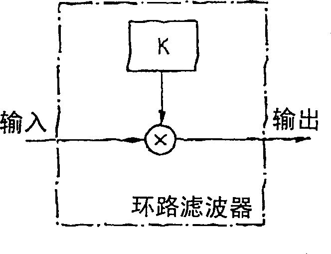
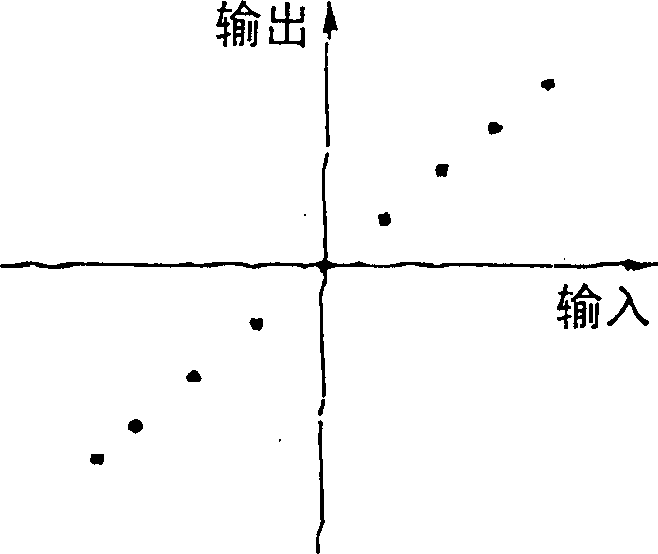
[0035] Fig. 3a shows a first embodiment of a loop filter with a non-linear transfer function for a PLL circuit according to the invention for canceling self-jitter in a received signal. The loop filter 1 depicted in Fig. 3 is digital. In an alternative embodiment, the loop filter is analog.

[0036] The digital loop filter 1 depicted in Fig. 3a is a non-linear P-regulator used in a PLL circuit according to the invention. The digital loop filter has a signal input 2 for receiving a digital data deviation signal via a signal line 3 . The phase difference signal applied to the signal input 2 is passed to the branch node 5 via the internal line 4 and controls the multiplexer 7 contained in the loop filter 1 via the internal control line 6 . The branch node 5 is also connected to a multiplier 9 via an internal line 8 . The output of multiplexer 7 is likewise connected via line 10 to multiplier 9 . Multiplier 9 multiplies the output value from multiplexer 7 by the phase differen...


PUM


Abstract

PLL circuit for eliminating self-jitter in a signal which is received by a control circuit, having a phase comparison circuit for producing a phase difference signal, which indicates the phase difference between the received signal and a fed-back output signal from the PLL circuit; having a loop filter for filtering the phase difference signal which is produced; having an oscillator, which is controlled by the filtered phase difference signal, for producing the output signal from the PLL circuit; with the loop filter having a nonlinear transfer function.

Description

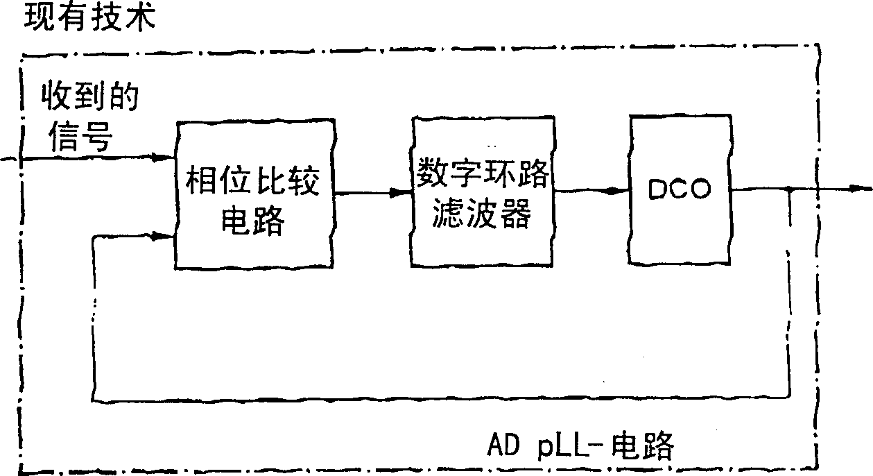
technical field [0001] The present invention relates to a PLL circuit for eliminating self-jitter in a signal received by a control circuit, in particular in a signal sent by a clock and data recovery circuit (CDR) in a receiver. Background technique [0002] figure 1 An ADPLL circuit (ADPLL: All Digital Phase Locked Loop) is shown according to the prior art. The PLL circuit can be analog or digital. The PLL circuit is a phase locked loop and is used to synchronize the frequency and phase of two oscillations. In this case, the PLL circuit mainly includes: a phase comparison circuit for generating a phase difference signal and determining the phase difference between the received signal and the feedback output signal from the PLL circuit; a downlink loop filter for filtering the resulting phase difference signal; and an oscillator controlled by the filtered phase difference and generating the output signal of the PLL circuit. [0003] Figure 2a shows the prior art used in...

Claims


Application Information

Patent Timeline
Patent Type & Authority Patents(China)
IPC IPC(8): H03L7/08H03L7/093H04L7/033
CPCH03L2207/50H03L7/093H04L7/0331
Inventor 约尔格·邦豪斯托马斯·杜达
Owner INTEL CORP
Why Eureka
Try Eureka