Rotational flow type water collection method

A swirl type and water eliminator technology, applied in water shower coolers, direct contact heat exchangers, heat exchange equipment, etc., can solve the problem of low water collection efficiency and achieve the effect of improving water collection efficiency

Inactive Publication Date: 2006-05-17
INST OF MECHANICS CHINESE ACAD OF SCI
View PDF0 Cites 0 Cited by
  • Summary
  • Abstract
  • Description
  • Claims
  • Application Information

AI Technical Summary

Problems solved by technology

[0003] The purpose of the present invention is to overcome the defect of low water collection efficiency in the above linear flow water collection method, and provide a swirl water collection method whose water collection efficiency is 20-50% higher than that of the linear flow water collection method

Method used


Image

  • Rotational flow type water collection method
  • Rotational flow type water collection method
  • Rotational flow type water collection method

Examples


Embodiment approach

[0025] The invention will be further described below in conjunction with the accompanying drawings and embodiments.

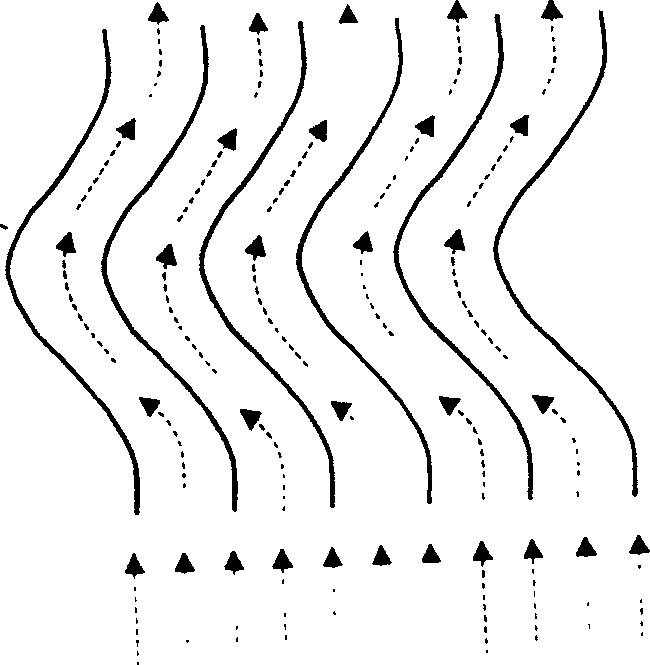
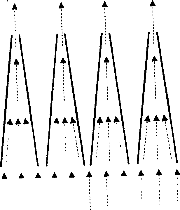
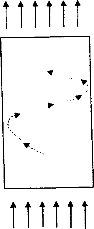
[0026] As can be seen from the figure, the method of the present invention uses a cylindrical water eliminator, which includes a cylindrical tube 2, and a pair of deflectors composed of a straight line side and an elliptical arc side placed crosswise to the straight line side are installed in the cylindrical tube 2. 3. The angle β between the guide plate 3 and the flow direction of the inlet of the moist air flow is 9.5°-79.3°, and its elliptical arc edge is in contact with the wall of the cylinder 2; the lower end of the cylinder 2 is equipped with an upper end of The circular lower end is a square base 4; the upper end of the cylindrical tube 2 is equipped with a fairing 1 with a certain thickness whose section is a grid; the side length of the square grid of the grid in the fairing 1 is 5 - 15%; the height of the base 4 is 1 / 10-7 / 10 of the diameter of the cy...


PUM


Abstract

The invention relates to a swirling water collecting method: under the guidance of a pair of straight line sides intersecting in a cylindrical water collector, an inclined flow guide plate composed of a straight line side and an elliptical arc side, the said flow guide plate The elliptical arc edge of the cylinder is in contact with the wall of the cylinder; the humid air flow changes from a straight line to a spiral flow, and the centrifugal force of the spiral flow is used to directly throw the granular water droplets in the wet air flow to the wall of the water collector Larger water droplets are formed to collect water; the diversion angle of the spiral flow of the moist air flow is 9.5°-79.3°, and the diversion angle is the angle between the spiral flow of the moist air flow and the air flow at the inlet of the moist air flow; The water collection efficiency of the swirl type water collection method provided by the invention can be increased by 20-50% compared with that of the linear air flow water collection method in the prior art.

Description

field of invention [0001] The invention relates to a water collection method widely used in industries such as metallurgy, petroleum, power, chemical industry, textile and large-scale central air-conditioning where water collection and energy saving are required, in particular to a swirling water collection method. Background technique [0002] Currently used in metallurgy, petroleum, power, chemical, textile, and large-scale central air-conditioning industries where water collection and energy saving are required. For example, water eliminators used in cooling towers include corrugated plate water eliminators and "eight-character" water eliminators. Plate type water eliminators, these water eliminators are baffle type water eliminators, when the humid air flow in the cooling tower flows in a straight line, it encounters the above-mentioned corrugated (baffle) plate or "eight" (baffle) plate and condenses into a Water is reclaimed; the water collectio...

Claims


Application Information

Patent Timeline
Patent Type & Authority Patents(China)
IPC IPC(8): F28C1/00F28F13/02
Inventor 鄂学全徐永君阚常珍
Owner INST OF MECHANICS CHINESE ACAD OF SCI
Why Eureka
Try Eureka