Swing spanner improved structure

A technology of swinging head and driving head, applied in the field of hand tool wrench, can solve the problems such as cracks in the meat wall, affecting the torque value of the wrench, damage and so on.

Inactive Publication Date: 2006-10-04
胡厚飞
View PDF0 Cites 1 Cited by
  • Summary
  • Abstract
  • Description
  • Claims
  • Application Information

AI Technical Summary

Problems solved by technology

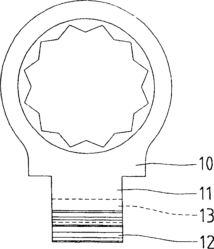
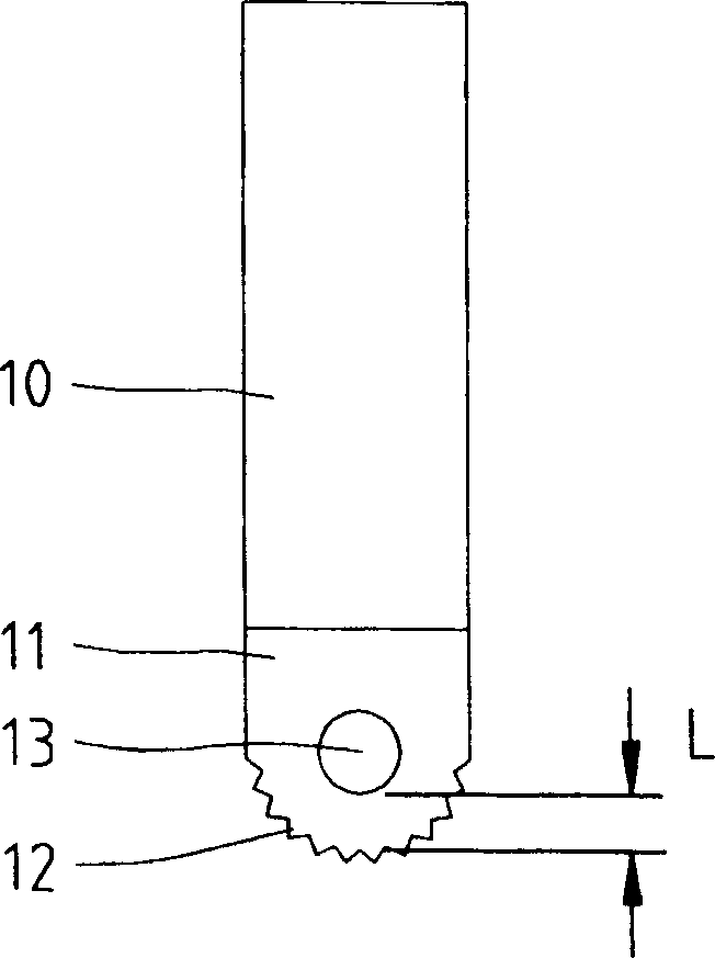
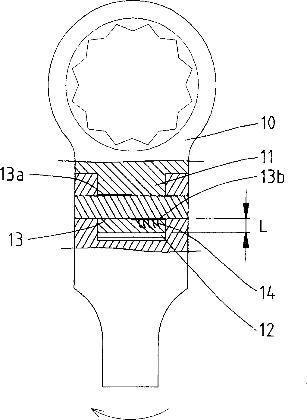
However, the meat thickness L1 of the stressed section 24b is greatly reduced due to structural limitations, so when the pulling force applied to the swing head wrench is too large, the meat wall of the stressed section 24b is prone to cracks 25 or damage, which seriously affects To the torque value that the wrench can bear

Method used


Image

  • Swing spanner improved structure
  • Swing spanner improved structure
  • Swing spanner improved structure

Examples


Embodiment Construction

[0052] Referring to FIG. 7 , according to the first embodiment of the present invention, the swing head wrench 30 can be used to turn a screw.

[0053] refer to Figure 8 , the swing head wrench 30 includes: a driving head 40, a handle 50 and a locking mechanism 60, one end of the driving head 40 is pivotally arranged on the handle 50, the locking mechanism 60 is located in the handle 50, and can be selected The relative pivotal relationship between the driving head 40 and the handle 50 is limited permanently.

[0054] The driving head 40 includes a first end and a second end, the first end can be used to drive the screw, the second end is provided with a pivot, and the outer edge of the pivot includes a first part and a second part, the The first part of the outer edge of the hub is provided with teeth, the arc surface of the second part of the hub is higher than the root of the tooth, and the position of the teeth of the first part is relatively located at the end of the wr...


PUM


Abstract

An improved structure of a tilting head spanner is composed of a tilting drive head with a screw part driving end and a convex pivoting end, and a handle with a concave end for pivoting to said convex pivoting end via a pin in order to tilt the head, and a control mechanism in it for controlling the tilting of head. Said convex pivoting head has the first part with teeth and the second part with arc surface for strengthening it.

Description

technical field [0001] The invention relates to a hand tool wrench, in particular to an improved structure of an oscillating head wrench composed of a driving head and a handle pivotally arranged on the driving head. Background technique [0002] Since human beings have civilization, hand tools have occupied a place, and since the invention of screws, wrenches have occupied the most important position in the field of hand tools, and are common in daily life, furniture, or machinery used in industry and commerce. , work tools, almost all use the cooperation of bolts and nuts or screw holes to achieve the purpose of fixing or locking. Therefore, the wrench used to lock or loosen bolts and nuts has become an indispensable tool for field workers. Indispensable hand tools, especially after the concept of DIY prevails, many consumers have their own tool sets with different usage characteristics for bolts and nuts of different shapes and sizes. [0003] refer to figure 1 and fi...

Claims


Application Information

Patent Timeline
Patent Type & Authority Patents(China)
IPC IPC(8): B25B23/00B25B13/46
Inventor 胡厚飞
Owner 胡厚飞
Why Eureka
Try Eureka