

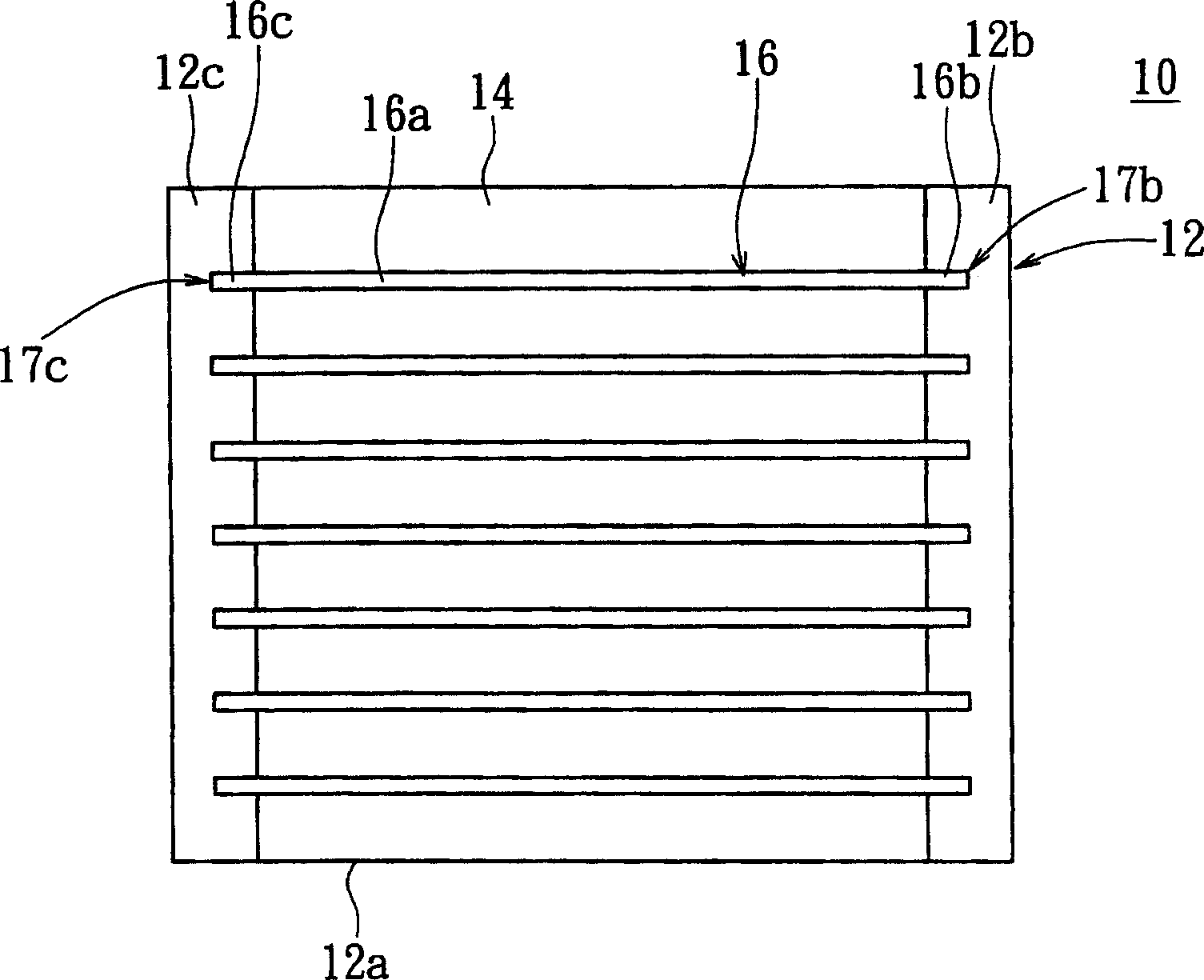
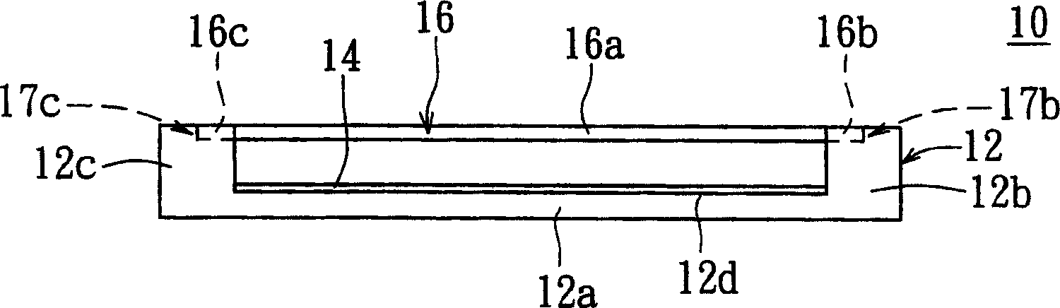
Backlight subassembly
A technology of backlight components and light-emitting parts, applied in optics, nonlinear optics, instruments, etc., which can solve the problems of shortened life of cold cathode tubes 16, difficult accumulation of mercury, poor brightness quality of backlight components 10, etc.
- Summary
- Abstract
- Description
- Claims
- Application Information
AI Technical Summary
Problems solved by technology
Method used
Image

Examples
Embodiment 1
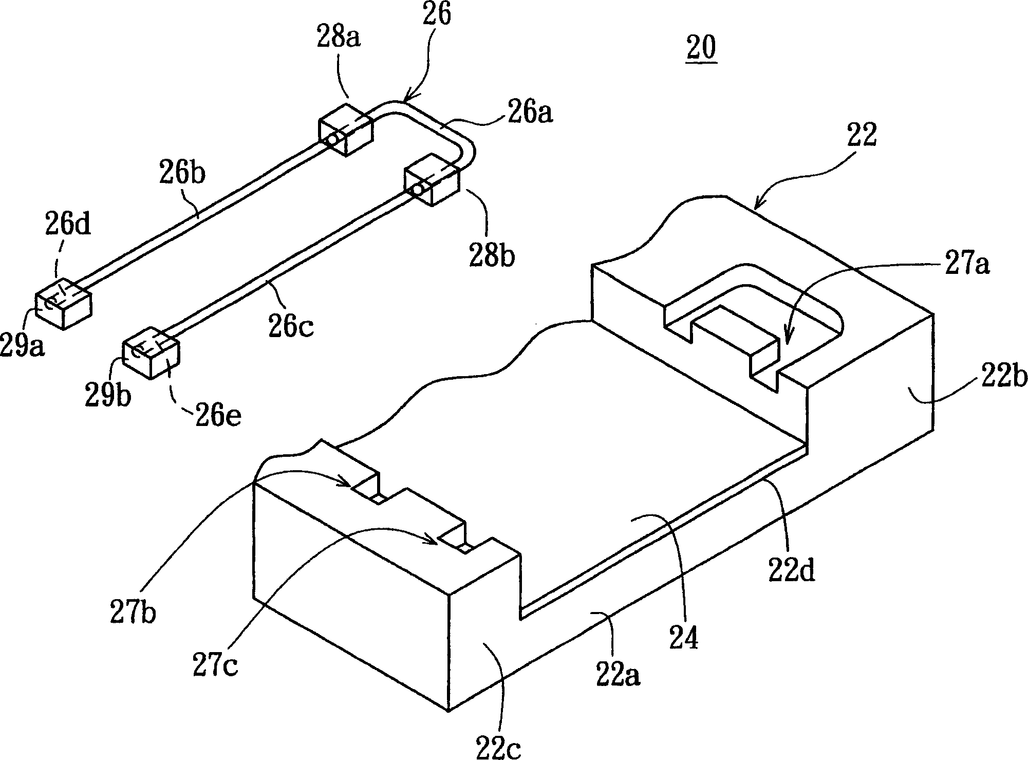
[0043] Also refer to Figure 2A and Figure 2B , Figure 2A is a partially exploded perspective view showing a backlight assembly according to Embodiment 1 of the present invention, Figure 2B is a partially assembled plan view showing a backlight assembly according to a preferred embodiment of the present invention. exist Figure 2A and Figure 2B Among them, the backlight assembly 20 at least includes a frame 22, a "U"-shaped lamp tube 26, a reflector 24, first heat dissipation structures 28a and 28b, and second heat dissipation structures 29a and 29b. The frame 22 includes a body portion 22a, a first support portion 22b and a second support portion 22c, the body portion 22a has a body portion top surface 22d, the first support portion 22b and the second support portion 22c are arranged on the body portion top surface on both ends of 22d. The top end of the first supporting portion 22b has a horseshoe-shaped receiving groove 27a, and the top end of the second supportin...
Embodiment 2
[0049] Also refer to Figure 3A and Figure 3B , Figure 3A is a partially assembled plan view showing a backlight assembly according to Embodiment 2 of the present invention, Figure 3B yes means Figure 3A Front view of the backlight assembly. exist Figure 3A and Figure 3B Among them, the difference between the backlight assembly 30 of the second embodiment and the backlight assembly 20 of the first embodiment is that the backlight assembly 30 further includes third heat dissipation structures 30a and 30b, and the third heat dissipation structures 30a and 30b respectively cover the light-emitting part of the straight tube The lower half of the central tube body of 26b and 26c is connected with the heat conduction of straight tube light emitting part 26b and 26c respectively, as Figure 3C shown. The other components of the backlight assembly 30 are the same as those of the backlight assembly 20 , and will not be repeated here.
[0050] It should be noted that the d...
Embodiment 3
[0053] Also refer to Figure 4A and Figure 4B , Figure 4A is a partially assembled front view showing a backlight assembly according to Embodiment 3 of the present invention, Figure 4B yes means Figure 4A Partial perspective exploded view of the straight tube light-emitting part and the fourth heat dissipation structure. exist Figure 4A and Figure 4B Among them, the difference between the backlight assembly 40 of the third embodiment and the backlight assembly 20 of the first embodiment is that the backlight assembly 40 includes fourth heat dissipation structures 40a and 40b. The fourth heat dissipation structures 40a and 40b are arranged on the reflecting plate 24 to support the lower half of the central tube body of the straight tube light emitting parts 26b and 26c respectively, and the fourth heat dissipation structures 40a and 40b are respectively connected to the straight tube light emitting parts. 26b and 26c are thermally connected. The other components of...
PUM
| Property | Measurement | Unit |
|---|---|---|
| wavelength | aaaaa | aaaaa |
Abstract
Description
Claims
Application Information