
Method and system for sequential calibration of matched current sources

一种电流源、编程电流的技术,应用在匹配电流源的顺序标定的系统及领域,能够解决改变基准电压、电流基准不匹配等问题

Inactive Publication Date: 2009-01-21
ACTIVE SEMI SHANGHAI +1
View PDF0 Cites 1 Cited by
  • Summary
  • Abstract
  • Description
  • Claims
  • Application Information

AI Technical Summary

Problems solved by technology

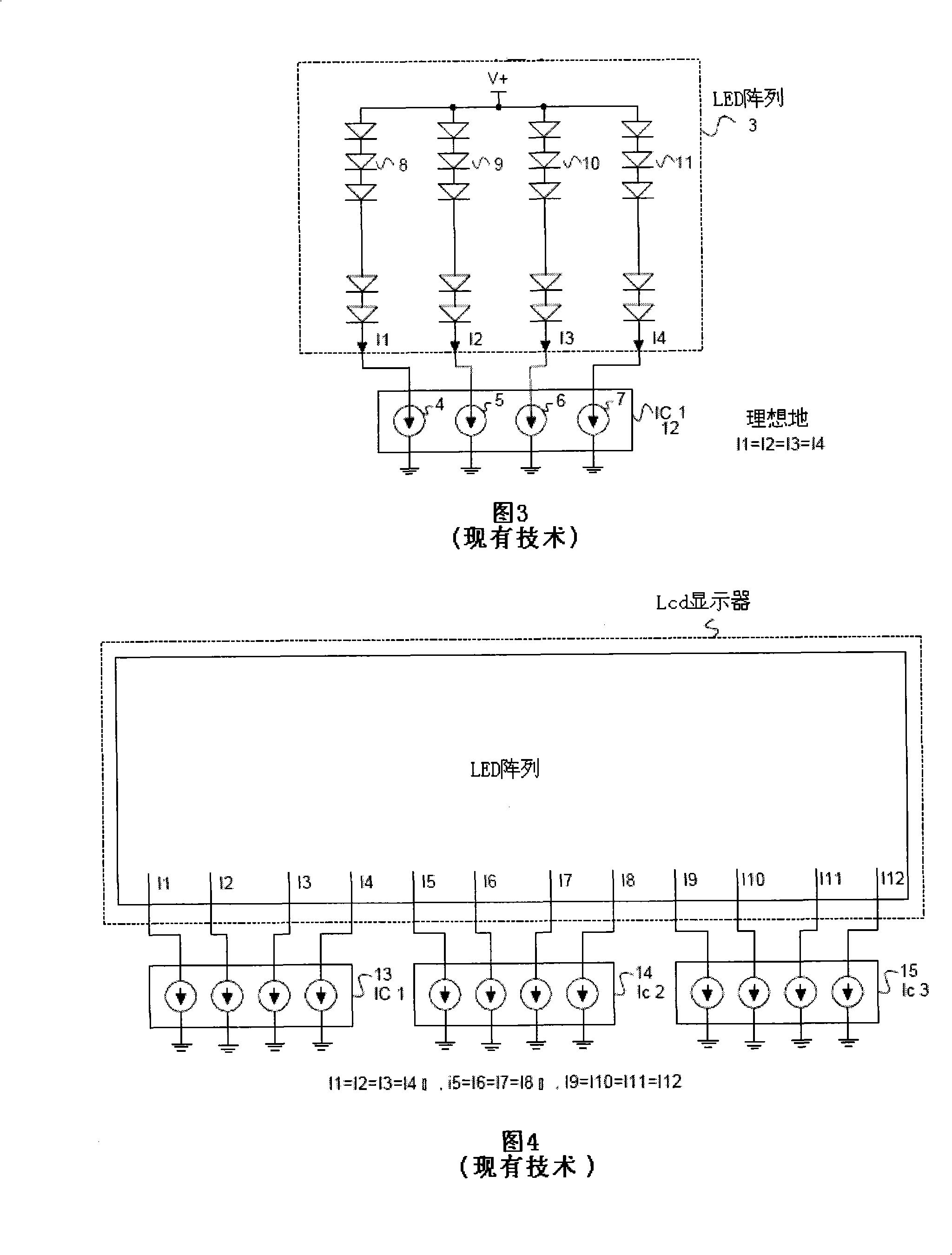
The problem is that the current reference of one integrated circuit 13 may not match the current reference of another integrated circuit 15 used in the same large array
The circuit of Figure 7 has some problems because the voltage drop along the ground line 34 of a large LCD display will effectively change the reference voltage that each integrated circuit "sees" as a person moves along the ground line 34 from integrated circuit to integrated circuit

Method used


Image

  • Method and system for sequential calibration of matched current sources
  • Method and system for sequential calibration of matched current sources
  • Method and system for sequential calibration of matched current sources

Examples


Embodiment Construction

[0051] Reference will now be made in detail to some embodiments of the invention, examples of which are illustrated in the accompanying drawings.

[0052] Figure 8 is a simplified circuit diagram of the first novel system 100 of the present invention. System 100 includes an LCD display 101 including an array of white light emitting diodes (WLEDs), a current reference 102, and a chain of three integrated circuits 103-105. Each of the LED currents I1-I12 flows through a corresponding one of the plurality of WLED strings 106-117. The integrated circuits 103-105 include a plurality of programmable current source circuits (CSCs) 118-129. The reference current IREF is delivered to each of the different CSCs one at a time to scale the LED current controlled by the CSC to match the reference current IREF. A reference current IREF enters one terminal of the integrated circuit and exits the other terminal so that the reference current can be used in successive integrated circuits fu...


PUM


Abstract

The present invention discloses a system and a method for sequential calibration of matched current sources. The system involves LED strings and programmable current source circuits (CSC). An LED current flows through each LED string. Each LED current is controlled by an associated programmable CSC. In one embodiment, the CSCs form a chain. A first CSC uses a reference current for calibration, and thereafter supplies the reference current to the next CSC. When the next CSC detects the reference current, it uses the reference current for calibration. CSCs are calibrated one by one down the chain. In a second embodiment, each CSC can receive the reference current from a common conductor. If the common conductor is detected to be available, then the CSC uses the reference current for calibration. When the conductor is in use, the other CSCs detect the conductor as unavailable and do not attempt to self-calibrate. The CSCs use the reference current one by one, but in an order that changes over time.

Description

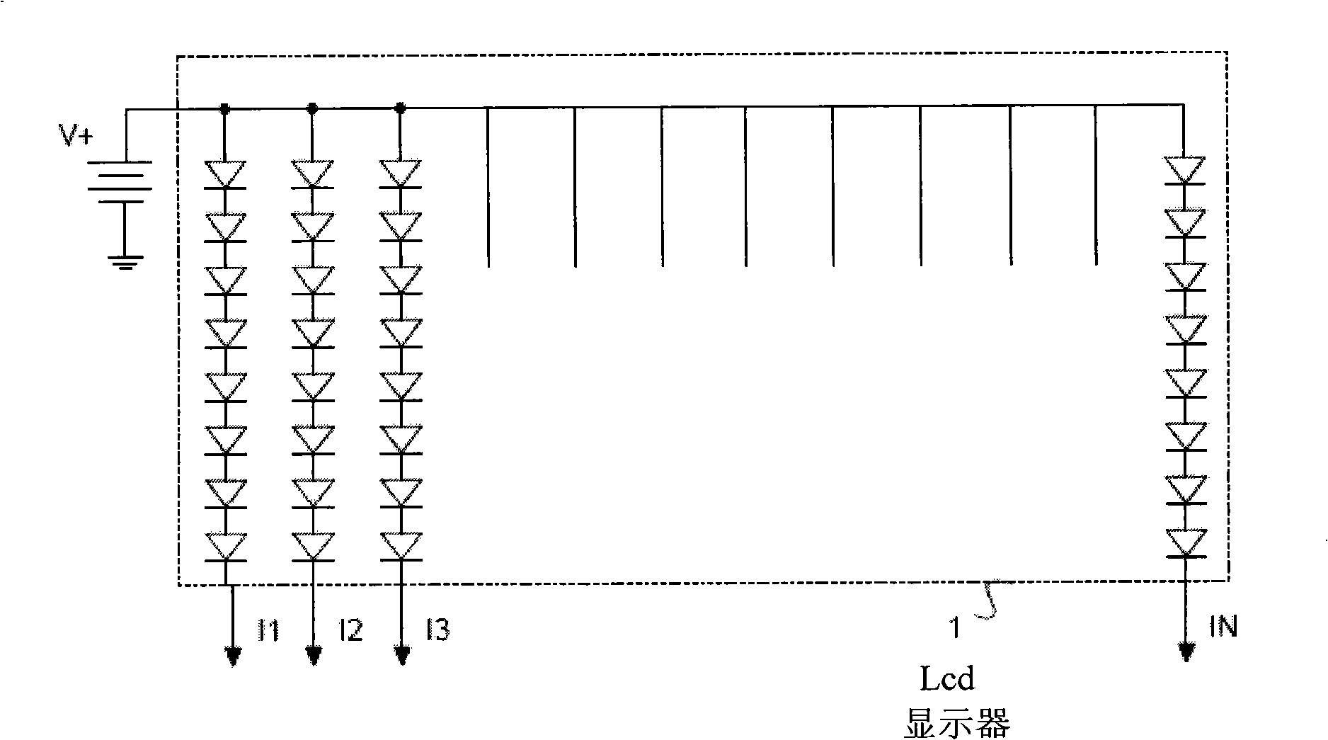
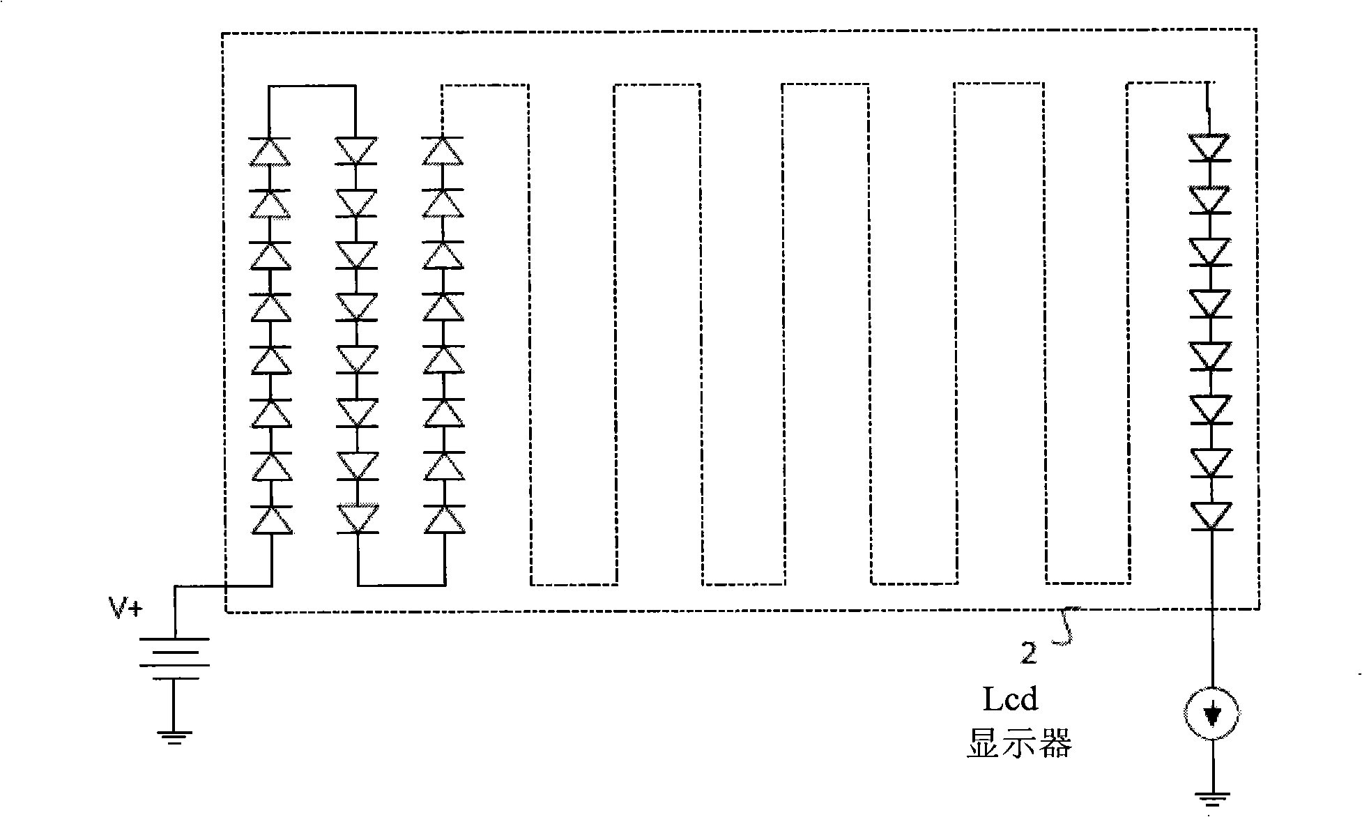
technical field [0001] The present invention relates generally to scaling current through a plurality of current sources, and more particularly to scaling current through strings of white light emitting diodes (WLEDs) for backlighting displays. Background technique [0002] New developments in WLED (White Light Emitting Diode) technology have resulted in cost-effective large-array WLEDs for backlighting applications in LCD screens for notebook computers, personal digital assistants, and flat-panel televisions. There are applications requiring hundreds of WLEDs today and thousands of WLEDs may be employed in future applications. [0003] These large arrays often consist of parallel connections of series strings of WLEDs. For example a typical array might have 12 parallel strings, with each string having ten WLEDs in series for a total of one hundred and twenty WLEDs. [0004] figure 1 (Prior Art) is a schematic diagram of an LCD display 1 employing 12 strings of WLEDs for ...

Claims


Application Information

Patent Timeline
Patent Type & Authority Applications(China)
IPC IPC(8): G09G3/36H05B37/00
CPCH05B33/0827H05B33/0812Y02B20/345H05B45/395H05B45/46Y02B20/30
Inventor 龚大伟黄树良理查德·格雷
Owner ACTIVE SEMI SHANGHAI
Learn More