
Backlight assembly

A technology of backlight components and light sources, applied in optics, nonlinear optics, instruments, etc., can solve problems affecting the brightness quality of backlight components 10, falling off, light leakage, etc.

Active Publication Date: 2009-05-06
AU OPTRONICS CORP
View PDF5 Cites 0 Cited by
  • Summary
  • Abstract
  • Description
  • Claims
  • Application Information

AI Technical Summary

Problems solved by technology

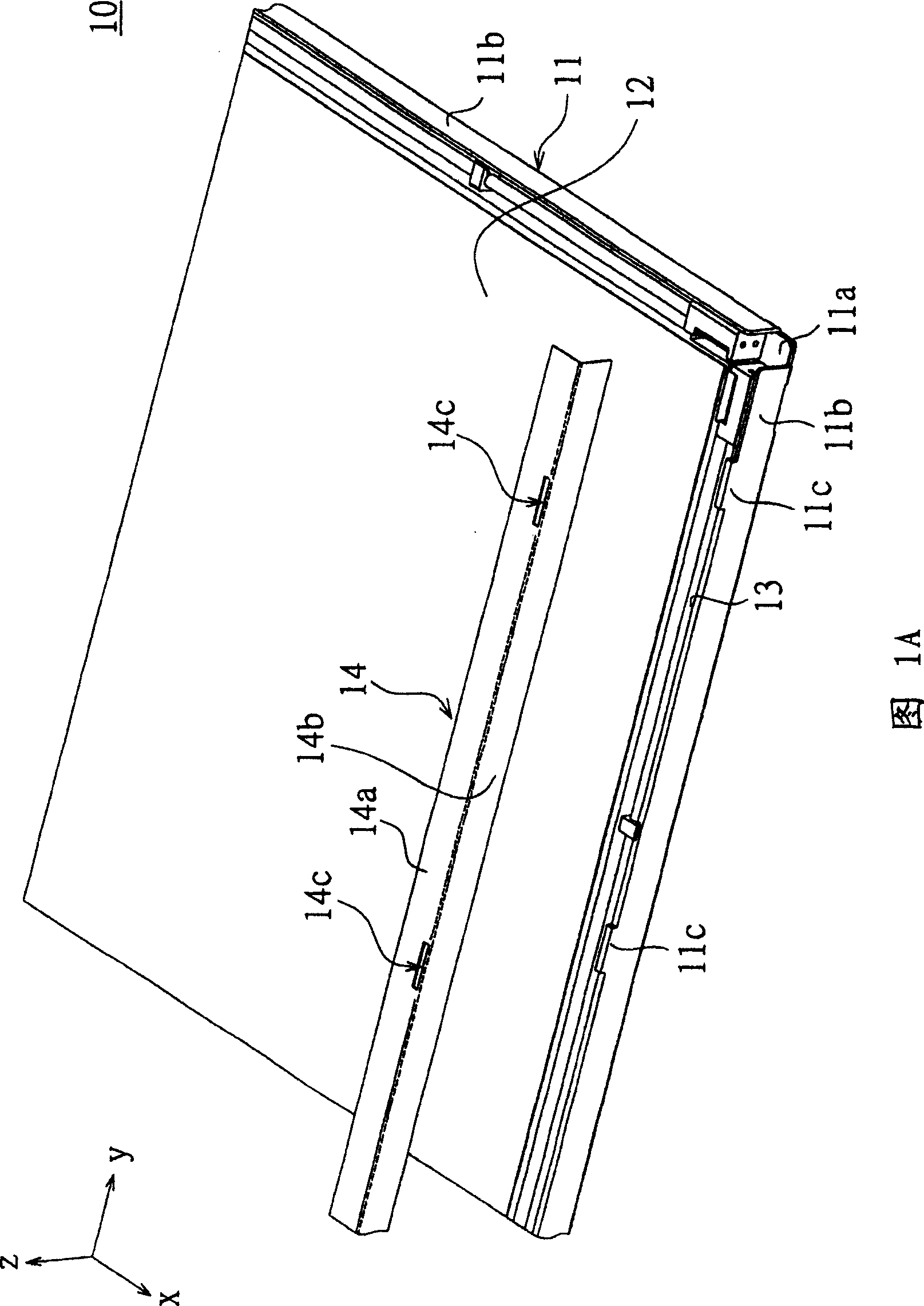
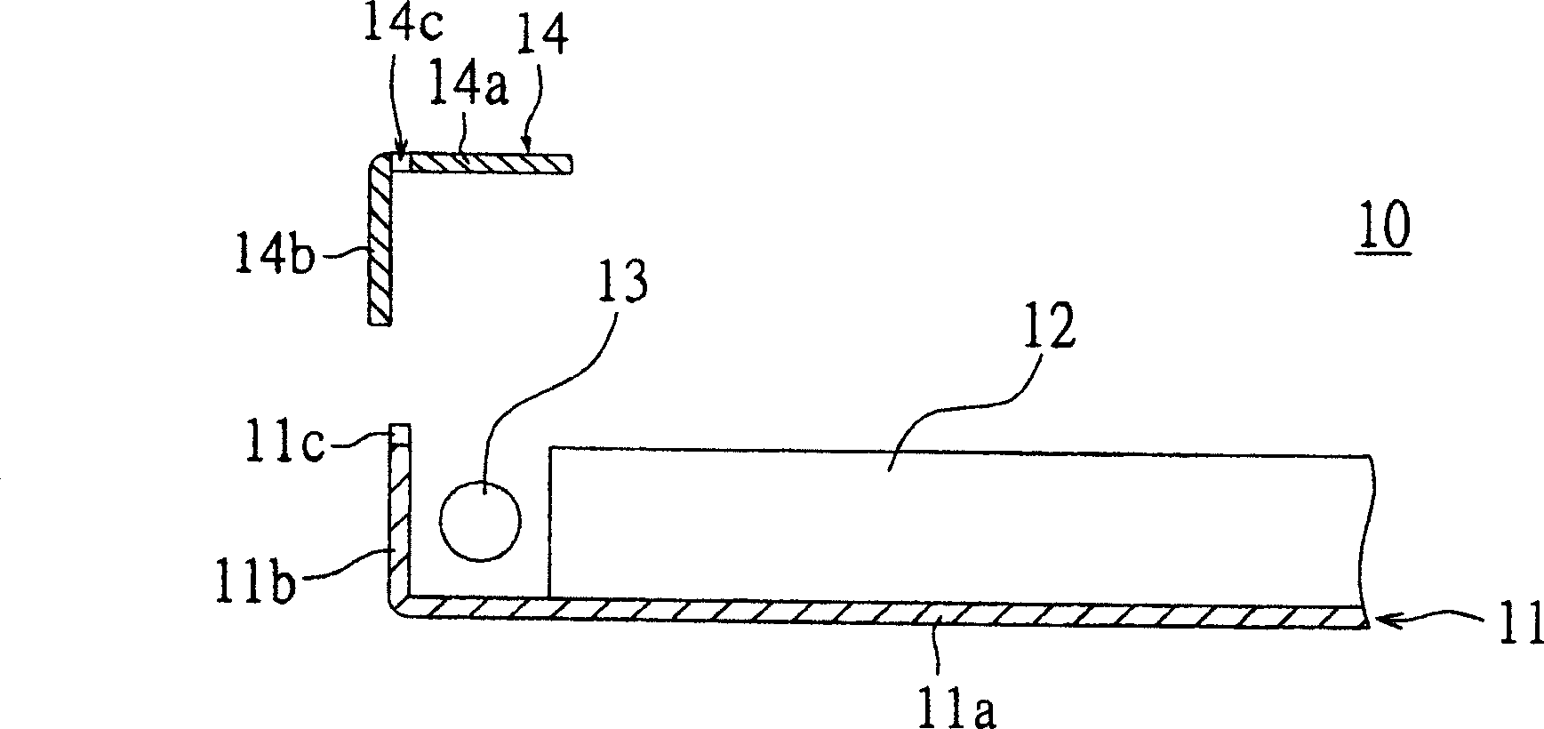
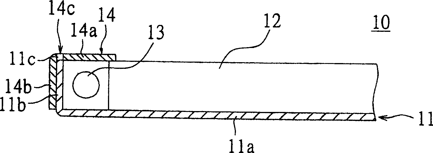
[0004] However, it should be noted that the raised positioning portion 11c and the positioning hole 14c are simply snapped together without any fastening and fixing design, so that when the reflector 14 is subjected to an external force, it is easy to fall off from the frame 11 along the z direction. phenomenon, such as Figure 1D shown
In this way, the light from the cold cathode tube 13 will be emitted through the gap between the top plate 14a of the reflector and the top surface of the light guide plate 12, resulting in so-called light leakage, which seriously affects the brightness quality of the backlight assembly 10.

Method used


Image

  • Backlight assembly
  • Backlight assembly
  • Backlight assembly

Examples


Embodiment Construction

[0042] Referring to FIG. 2, FIG. 2 is a partially exploded view showing a backlight assembly according to a preferred embodiment of the present invention. In FIG. 2 , the backlight assembly 20 at least includes a bezel 21 , a light guide plate (LGP) 22 , a light source 23 and a reflective shell 24 . The frame 21 has a connected frame bottom plate 21a and a plurality of frame side plates 21b. The outer surface of the frame side plate 21b has at least one fastening structure 21c. The light guide plate 22 is disposed on the frame bottom plate 21 a and is separated from the frame side plate 21 b by a distance. The light source 23 is disposed on the frame bottom plate 21 a and is located between the frame side plate 21 b and the light guide plate 22 . The reflector 24 has a reflector top plate 24a and a reflector side plate 24b connected thereto. The reflector side plate 24b has at least one fastening hole 24c, and the fastening hole 24c is like a “T”-shaped opening.

[0043] Als...


PUM


Abstract

Backlight assemble includes a frame and a reflection cover. The frame includes back plane, side plates and clip connection structure. The side plates are connected to the back plane. The clip connection structure is setup on surface of a side plate. The reflection cover includes top plate and side plates. A side plate of the reflection cover possesses a clip connection hole. The clip connection hole and the clip connection structure make the reflection cover and the frame be combined closely.

Description

technical field [0001] The present invention relates to a backlight module, and in particular to a backlight module that can be tightly combined with a reflector and a frame. Background technique [0002] With the rapid progress of liquid crystal display (liquid crystal display, LCD) production technology, and its advantages of lightness, lightness, power saving, and radiation-free, the liquid crystal display is widely used in personal digital assistants (personal digital assistants, PDAs). ), notebook computers, digital cameras, digital video cameras, mobile phones, computer screens and LCD TVs and other electronic products. Coupled with the industry's active investment in research and development and the adoption of large-scale production equipment, the quality of liquid crystal displays has been continuously improved, and the price has been continuously reduced, thus rapidly expanding the application field of liquid crystal displays. However, since the liquid crystal dis...

Claims


Application Information

Patent Timeline
Patent Type & Authority Patents(China)
IPC IPC(8): G02F1/1335G02F1/13357
Inventor 蔡宜轩王明发
Owner AU OPTRONICS CORP
Learn More