Check patentability & draft patents in minutes with Patsnap Eureka AI!

Electromagnetic contactor

A technology of electromagnetic contactor and electromagnetic coil, which is applied in the direction of electromagnetic relay, relay, detailed information of electromagnetic relay, etc., can solve the problem of increasing the size of electromagnetic contactor, and achieve the effect of low cost

Inactive Publication Date: 2007-01-24
FUJI ELECTRIC FA COMPONENTS & SYST CO LTD
View PDF2 Cites 3 Cited by
  • Summary
  • Abstract
  • Description
  • Claims
  • Application Information

AI Technical Summary

Problems solved by technology

In addition, when reducing the spring constant K by increasing the plate thickness of the buffer material, the fixed core must be placed at a higher position, which increases the size of the electromagnetic contactor

Method used


Image

  • Electromagnetic contactor
  • Electromagnetic contactor
  • Electromagnetic contactor

Examples


Embodiment Construction

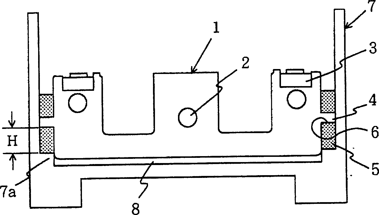
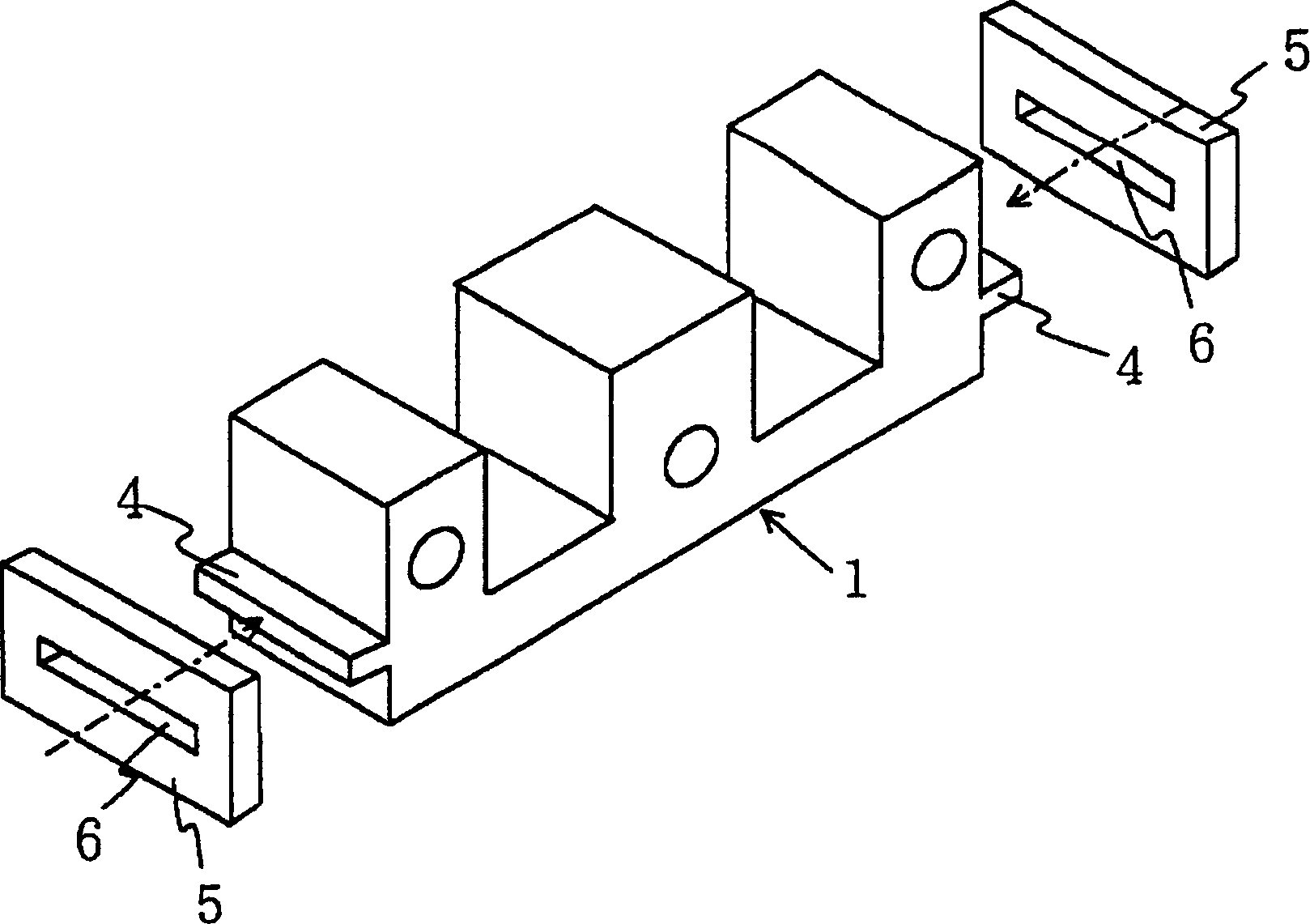
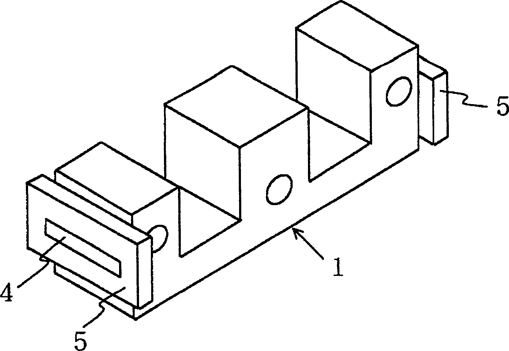
Figure 1-3 A basic embodiment of the invention is shown in which figure 1 It is a cross-sectional view showing the fixed iron core installed in the bottom box of the AC electromagnetic contactor, figure 2 is an exploded perspective view showing the figure 1 The fixed core and buffer material in the image 3 is a perspective view showing the combination of the fixed core and the cushioning material. exist Figure 1-3 Among them, the fixed iron core 1 is E-shaped, and as it is known, it is made of many silicon steel sheets punched into the shape shown and fastened to each other with rivets 2 and the shielding coil 3 ( figure 1 ) are attached to the respective magnetic poles of the left and right legs. In this embodiment, the rectangular boss 4 is integrally formed with the left and right end surfaces of the fixed core 1 and punched out at the same time.

[0019]

On the other hand, reference numeral 5 refers to a rectangular plate-like cushioning material which is int...


PUM


Abstract

Provided is a bumper mechanism for a fixed iron core which has a good cushion action and is compact in size.Protrusions 4 are formed integrally with both end surfaces of the fixed iron core 1, a buffer material 5 made of a sheet material is vertically mounted to this protrusion 4, and the fixed iron core 1 is supported on a lower case 7 of the electromagnetic contactor using this buffer material 5 as a supporting leg. By vertically using the sheet-shaped buffer material 5, a spring height H can be easily increased to provide the good cushion action. If there is space as large as the sheet thickness of the buffer material 5 on both sides of the fixed iron core 1, the buffer material can be mounted to save space, In addition, the buffer material 5 can be formed by stamping the sheet material to reduce manufacturing cost.

Description

[0001] [0001] technical field [0002] The present invention relates to an electromagnetic contactor for switching on and off of a contact mechanism through an electromagnet, and more particularly relates to a buffer structure of the electromagnet. [0003] [0002] Background technique [0004] An electromagnetic contactor is usually composed of an electromagnet, which includes a fixed iron core and a moving iron core. They are placed opposite each other in an insulating casing. The insulating casing is composed of a top box and a bottom box. In terms of structure, the electromagnetic coil is attached to the bottom box. The fixed iron core is supported, and the moving iron core is connected with a contact mechanism. When the electromagnetic coil is excited, the moving iron core will overcome the elastic force of the return spring and attach to the fixed iron core, thereby switching the contact mechanism. In this electromagnetic contactor, when the moving iron core is attract...

Claims


Application Information

Patent Timeline
Patent Type & Authority Patents(China)
IPC IPC(8): H01H50/36H01H50/30
CPCH01H50/305
Inventor 和田正义吉本博
Owner FUJI ELECTRIC FA COMPONENTS & SYST CO LTD
Features
  • R&D
  • Intellectual Property
  • Life Sciences
  • Materials
  • Tech Scout
  • Unparalleled Data Quality
  • Higher Quality Content
  • 60% Fewer Hallucinations
Learn More