Fluid valve device

A technology for fluid valves and shells, applied in valve devices, valve operation/release devices, valve details, etc., can solve problems that affect work efficiency and production costs, still fall, non-assembly and disassembly, etc.

Inactive Publication Date: 2007-05-16
MIKUNI CORP
View PDF8 Cites 0 Cited by
  • Summary
  • Abstract
  • Description
  • Claims
  • Application Information

AI Technical Summary

Problems solved by technology

[0005] In addition, in the traditional fluid valve, the valve seat of the hydraulic control solenoid valve is on the channel housing, and the sealing between the hydraulic control valve and the valve seat can only be checked after the hydraulic control solenoid valve is installed on the channel housing, which is not suitable , the valve seat must be disassembled and reprocessed or the channel housing must be removed
The result is unnecessary assembly and disassembly operations, affecting work efficiency and production costs

Method used


Image

  • Fluid valve device
  • Fluid valve device
  • Fluid valve device

Examples


Embodiment Construction

[0032] Embodiments of the present invention will be described below with reference to the drawings.

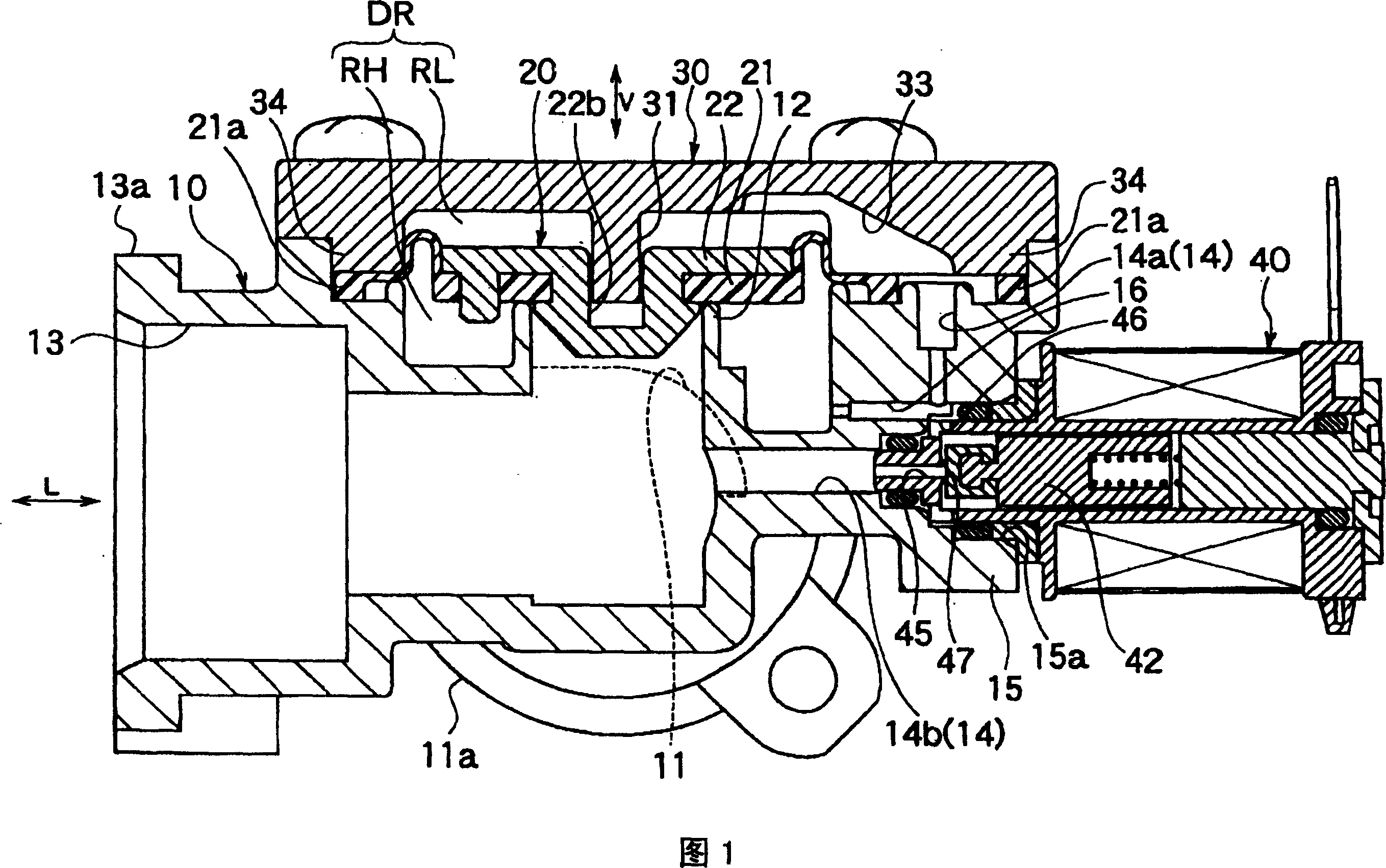
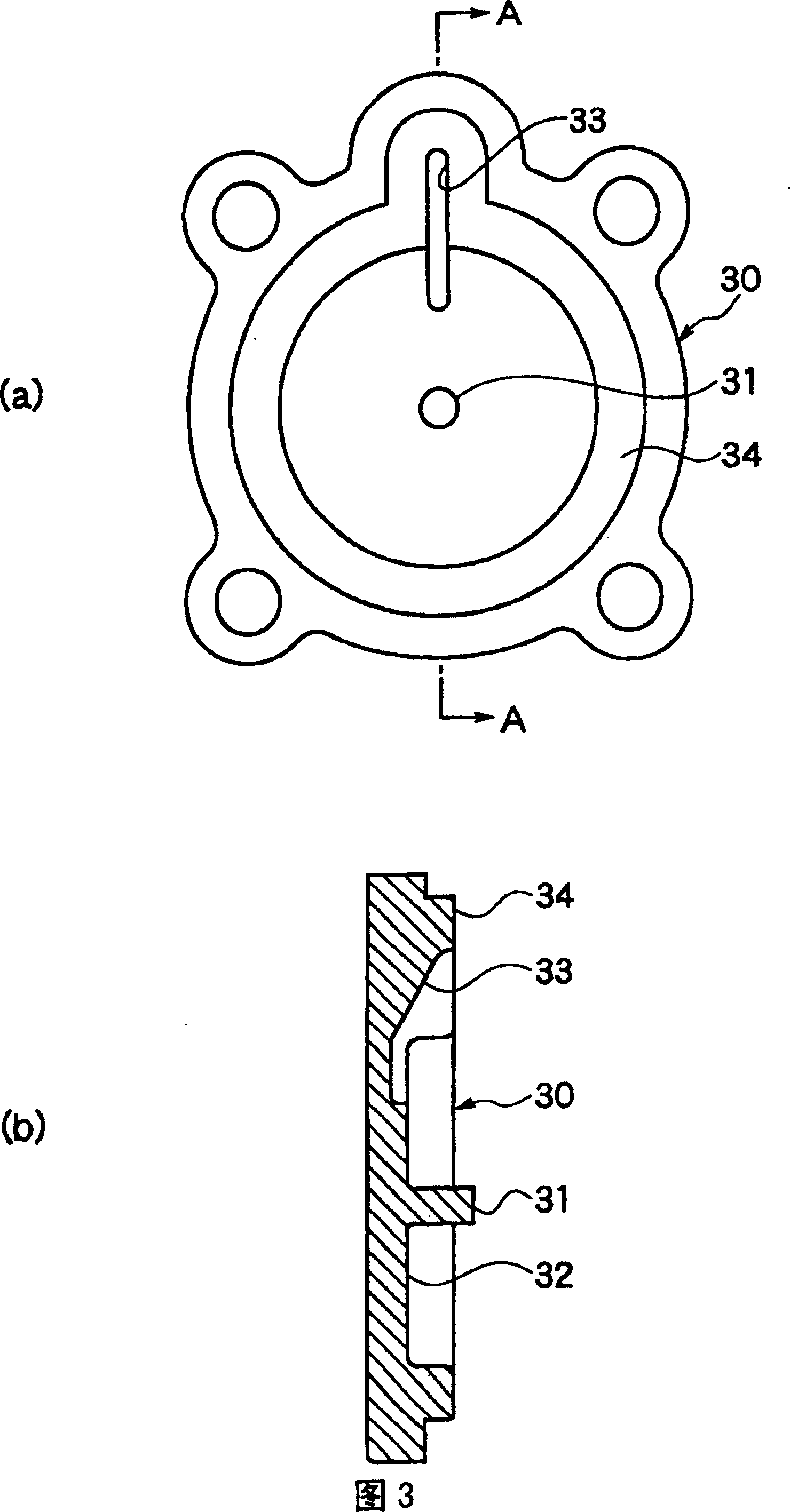
[0033] 1 and 4 show an embodiment of the fluid valve of the present invention. This fluid valve has the channel housing 10 of the inflow channel and the outflow channel of dividing fluid (being water here), the diaphragm valve 20 installed in the channel housing 10, is connected with the channel housing 10 of division diaphragm valve 20 back pressure chambers The valve cover 30 and the hydraulic control solenoid valve 40 connected with the channel housing 10 .

[0034] As shown in FIG. 1 and FIG. 2 , the channel housing 10 is composed of an inflow channel 11 extending rearward in FIG. The outflow passage 13 of the back pressure chamber RL and the outflow passage 13 are connected with the hydraulic control passage 14 and the flange 15 for installing the hydraulic control solenoid valve 40 is formed. Flange portions 11 a , 13 a connected to pipes are formed at opening ends of ...


PUM


Abstract

An fluid valve device with a pilot solenoid valve comprises a passage body 10 for determining an inflow passage 11 and an outflow passage 13, a diaphragm valve 20 interposed between the inflow passage 11 and the outflow passage 13 for opening / closing the passage, a communication passage 16 for communicating a front pressure chamber RH and a back pressure chamber RL of the diaphragm valve 20, a pilot passage 14 for communicating the back pressure chamber RL and the outflow passage 13, the pilot solenoid valve 40 for opening / closing the pilot passage 14 and a flat plate type cover 30 connected with the passage body 10 in order to determine the back pressure chamber RL. The pilot solenoid valve 40 is connected with the passage body 10 in a region out of the cover 30 and a groove passage 33 is formed on the cover 30 for determining a part of the pilot passage. Thereby, the device is restricted from protruding above the back pressure chamber RL and the device can be miniaturized and thin- walled.

Description

technical field [0001] The present invention relates to a fluid valve for controlling fluid flow, in particular an electromagnetically driven hydraulic control solenoid valve and a diaphragm valve for opening and closing a fluid channel. Background technique [0002] Traditional fluid valves for water supply and drainage of water heaters and washing machines include JP-A-6-117570, Utility Model Registration No. 2519305, and the like. The fluid valve disclosed in these patents has a channel housing that divides the inflow channel and the outflow channel of water, a diaphragm valve that opens and closes the channel between the two channels, and an electromagnetic drive that controls the pressure in the back pressure chamber of the diaphragm valve to open and close the diaphragm valve. Hydraulic control solenoid valve, etc. These fluid valves can be installed, for example, in indoor underfloor or sidewall spaces, and where space is limited for equipment such as washing machine...

Claims


Application Information

Patent Timeline
Patent Type & Authority Patents(China)
IPC IPC(8): F16K7/17F16K31/06F16K31/126
Inventor 菅原利光久保田贤一横泽文隆川村光
Owner MIKUNI CORP
Why Eureka
Try Eureka