A high-precision and high-efficiency monolithic two-degree-of-freedom microgripper for optical fiber assembly

A degree of freedom, micro-clamp technology, applied in workpiece clamping devices, manufacturing tools, etc., can solve the problems of complex MEMS optical switches, serious assembly problems, component damage, etc., to achieve convenient and high-precision positioning, eliminating the assembly process, function Rich and flexible effects

Inactive Publication Date: 2015-09-30
BEIHANG UNIV
View PDF6 Cites 0 Cited by
  • Summary
  • Abstract
  • Description
  • Claims
  • Application Information

AI Technical Summary

Problems solved by technology

[0003] However, since MEMS chips and optical fibers are vulnerable components, their integrated assembly must not only consider the coupling efficiency of optical fibers, but also consider the damage of these components during the assembly process.
As a result, the assembly of MEMS optical switches often requires a complex and sophisticated micro-operating system, resulting in high packaging costs, which affects the application and popularization of MEMS optical switches.
The assembly problem is even more severe for U-groove MEMS optical switches with high reliability and high optical coupling efficiency

Method used


Image

  • A high-precision and high-efficiency monolithic two-degree-of-freedom microgripper for optical fiber assembly
  • A high-precision and high-efficiency monolithic two-degree-of-freedom microgripper for optical fiber assembly
  • A high-precision and high-efficiency monolithic two-degree-of-freedom microgripper for optical fiber assembly

Examples


Embodiment Construction

[0048] The present invention will be further described in detail below in conjunction with the accompanying drawings.

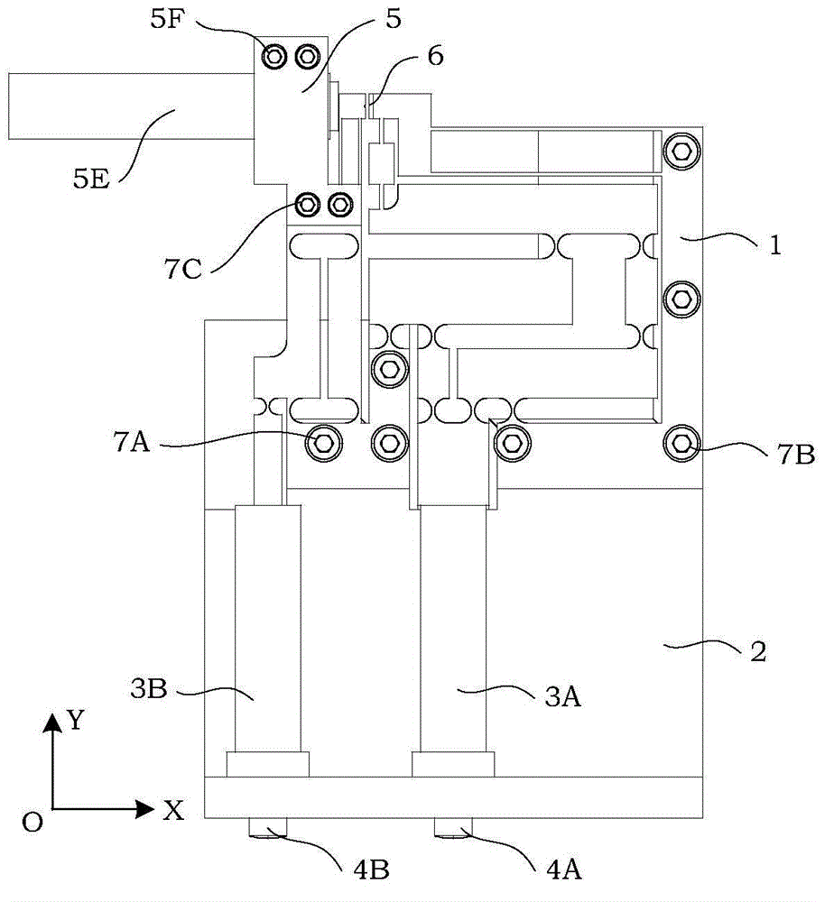
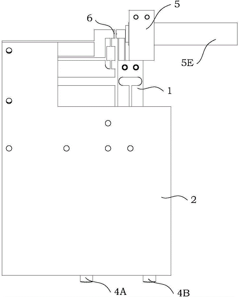
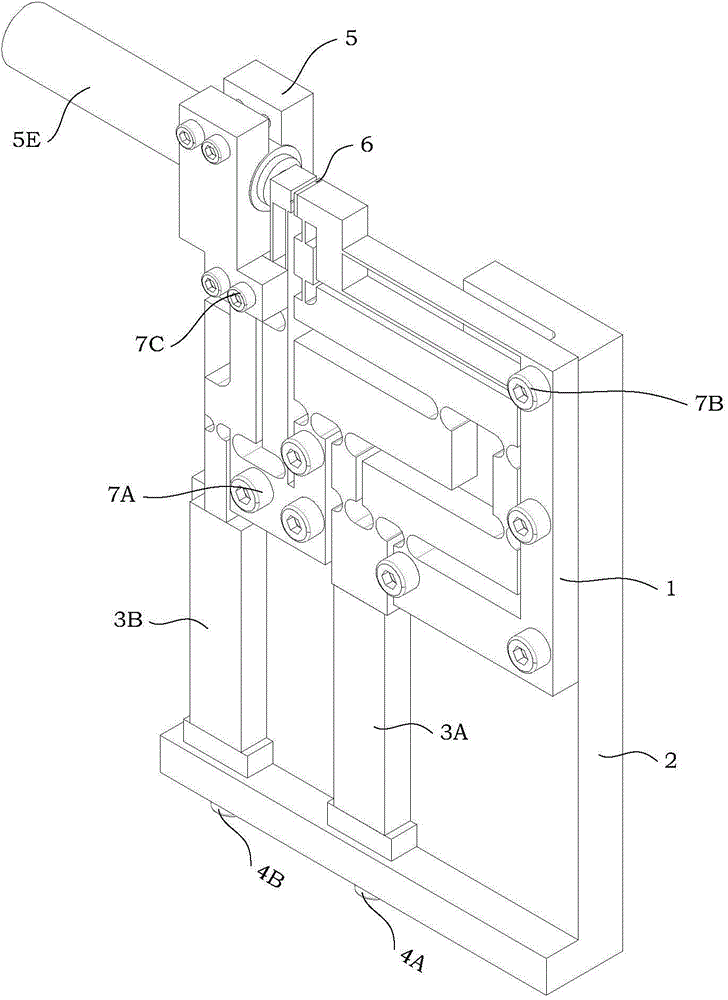
[0049] see figure 1 , Figure 1A , Figure 1B and Figure 1C As shown, a high-precision and high-efficiency monolithic two-degree-of-freedom micro gripper designed by the present invention for optical fiber assembly includes a capacitive sensor 5A, a piezoelectric ceramic driver 3A , B piezoelectric ceramic driver 3B, motion transmission mechanism 1, base 2, sensor mount 5, glass patch 6, pre-tightening bolts and fixing bolts.

[0050] Piezo driver

[0051] see figure 1 , Figure 1B and Figure 1C As shown, the A piezoelectric ceramic driver 3A is installed between the first input board 1A of the motion transmission mechanism 1 and the second panel 2B of the base 2, and the A piezoelectric ceramic driver 3A and the second panel 2B of the base 2 A B block 3D is placed between them.

[0052] see figure 1 , Figure 1B and Figure 1C As shown, the B p...


PUM


Abstract

The invention discloses a high-accuracy and high-efficiency monolithic two-degree-of-freedom micro-gripper for assembling an optical fiber. The monolithic two-degree-of-freedom micro-gripper comprises a capacitive sensor, a piezoelectric ceramics actuator A, a piezoelectric ceramics actuator B, a motion transmission mechanism, a base, a sensor mounting base, a glass patch, a pre-tightening bolt and a fixing bolt. The motion transmission mechanism is arranged above a concave cavity formed in the base, the sensor mounting base is arranged on the left upper side of the base, and the glass patch is arranged on an inner side panel of a second output plate; the output force of the piezoelectric ceramics actuator A and the piezoelectric ceramics actuator B is distributed along a Y axis, and the two piezoelectric ceramics actuators are placed in parallel; the capacitive sensor is used for sensitively measuring the displacement change of the first output plate on an X axis, and is arranged on the sensor mounting base. By adopting the high-accuracy and high-efficiency monolithic two-degree-of-freedom micro-gripper, problems concerning heavy clamping and rubbing specific to alignment of the rotating angle in the assembling process of a polarization maintaining fiber are solved, meanwhile the assembling efficiency is increased on the premise of ensuring the aligning accuracy of the rotating angle of the polarization maintaining fiber, and the production cost is effectively reduced.

Description

technical field [0001] The invention relates to a micro-clamp mechanism, more particularly, a novel high-precision and high-efficiency monolithic two-degree-of-freedom micro-clamp for optical fiber assembly. Background technique [0002] The optical switch (or MEMS optical switch) based on MEMS (Micro-Electro-Mechanical-Systems) chips is a composite system integrating silicon chips and optical fibers, which is used for optical path switching in a new generation of all-optical communication networks . [0003] However, since MEMS chips and optical fibers are fragile components, their integrated assembly must not only consider the coupling efficiency of optical fibers, but also consider the damage of these components during the assembly process. As a result, the assembly of MEMS optical switches often requires a complex and precise micro-operating system, resulting in high packaging costs, which affects the application and popularization of MEMS optical switches. For U-groov...

Claims


Application Information

Patent Timeline
Patent Type & Authority Patents(China)
IPC IPC(8): B25B11/02
CPCB25B11/02
Inventor 张建斌卢康康陈伟海蒋俊
Owner BEIHANG UNIV
Why Eureka
Try Eureka