
An anti-falling optical cable down-conductor clamp

A down-conductor and anti-dropping technology, which is applied in the direction of power cables, cables, and power cables including optical transmission components, can solve the problems of single structure of down-conductor clamps, poor stability of down-conductor clamps, and low practicability. Achieve the effect of convenient operation, not easy to fall off, and high practicability

Active Publication Date: 2021-11-09
STATE GRID SHANDONG ELECTRIC POWER +1
View PDF0 Cites 0 Cited by
  • Summary
  • Abstract
  • Description
  • Claims
  • Application Information

AI Technical Summary

Problems solved by technology

[0002] At present, in the erection of high-voltage and ultra-high-voltage transmission lines in China, most of the ground wires use optical fiber composite overhead ground wires to protect the transmission lines. Due to its communication function, OPGW has always adopted the tower-by-tower grounding operation mode to prevent The natural down-leading of the lightning down-leading means that the received lightning current is led to the grounding device through the method of lightning protection down-leading. Under the external environment, the carelessness of the construction personnel and other factors, the OPGW optical cable falls out of the clamping groove, and the OPGW optical cable contacts the ground wire, causing a short circuit and power failure;
[0003] However, the structure of the existing down-lead clamp is single and fixed, which cannot hold and fix the optical cable well, and the optical cable is prone to fall off, and the down-conductor clamp itself has poor stability and low practicability

Method used


Image

  • An anti-falling optical cable down-conductor clamp
  • An anti-falling optical cable down-conductor clamp
  • An anti-falling optical cable down-conductor clamp

Examples


Embodiment Construction

[0026] The following will clearly and completely describe the technical solutions in the embodiments of the present invention with reference to the accompanying drawings in the embodiments of the present invention. Obviously, the described embodiments are only some, not all, embodiments of the present invention.

[0027] Unless otherwise defined, the technical terms or scientific terms used herein shall have the usual meanings understood by those skilled in the art to which the present invention belongs. "First", "second" and similar words used in the patent specification and claims of the present invention do not indicate any order, quantity or importance, but are only used to distinguish different components. Likewise, words like "a" or "one" do not denote a limitation in quantity, but indicate that there is at least one.

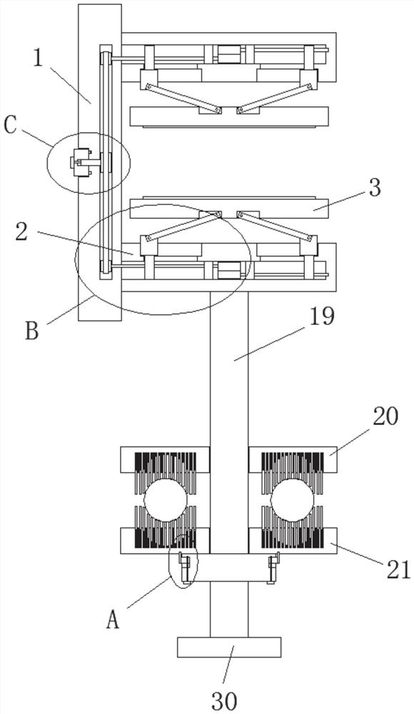
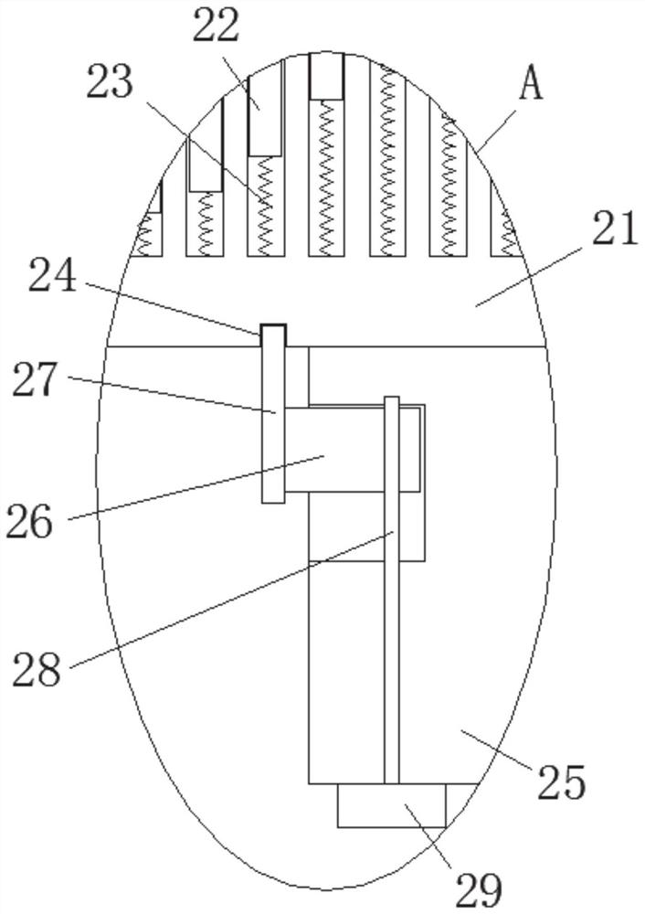
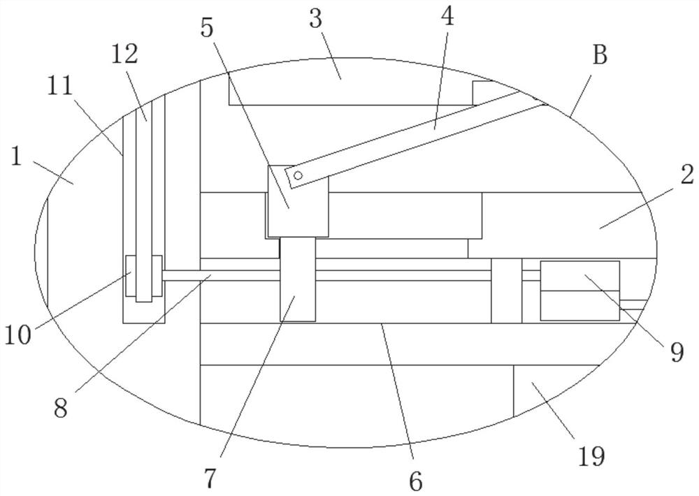
[0028] refer to Figure 1-7, an anti-drop-off optical cable down-conductor clamp, including a connecting plate 1, two side seat plates 2 are fixedly ins...


PUM


Abstract

The invention belongs to the field of optical cable equipment, in particular to an anti-shedding optical cable down-conductor clamp. The structure of the existing down-conducting clamp is single and fixed, which cannot clamp and fix the optical cable well, and the optical cable is prone to fall off, and the down-conductor The cable clamp itself has poor stability and low practicability. Now the following scheme is proposed, which includes a connecting plate. Two side seat plates are fixedly installed on one side of the connecting plate. One side where the two side seat plates are close to each other There are anti-off splints on both sides, and adjustment units are provided on the two side seats. The adjustment units are matched with the corresponding anti-off splints. block and two first screw rods. The structure of the invention is reasonable, the structure of the down conductor clamp is rich and flexible, the optical cable can be better clamped and fixed, the optical cable is not easy to fall off, the versatility is good, and it is convenient to clamp cables of different shapes, and the down conductor clamp It has good stability and high practicability.

Description

technical field [0001] The invention relates to the technical field of optical cable equipment, in particular to an anti-dropping optical cable down-conductor clip. Background technique [0002] At present, in the erection of high-voltage and ultra-high-voltage transmission lines in China, most of the ground wires use optical fiber composite overhead ground wires to protect the transmission lines. Due to its communication function, OPGW has always adopted the tower-by-tower grounding operation mode to prevent The natural down-leading of the lightning down-leading means that the received lightning current is led to the grounding device through the method of lightning protection down-leading. Under the external environment, the carelessness of the construction personnel and other factors, the OPGW optical cable falls out of the clamping groove, and the OPGW optical cable contacts the ground wire, causing a short circuit and power failure; [0003] However, the existing down-c...

Claims


Application Information

Patent Timeline
Patent Type & Authority Patents(China)
IPC IPC(8): H01R11/14H01R4/42H01B9/00
CPCH01B9/005H01B9/008H01R4/42H01R11/14
Inventor 林建李珊孙占龙李中凯魏亮赵龙王廷平王久成孙京锋姜楠刘洋
Owner STATE GRID SHANDONG ELECTRIC POWER
Learn More