Electrode assembly for the removal of surface oxides by electron attachment
A technology of oxides and components, applied in the direction of electrical components, electrical solid devices, printed circuits assembled with electrical components, etc., can solve problems such as changing electric fields and hindering precise control
- Summary
- Abstract
- Description
- Claims
- Application Information
AI Technical Summary
Problems solved by technology
Method used
Image

Examples
Embodiment 1
[0083] A first experiment was performed using a laboratory scale furnace. The sample used was a fluxless tin-lead solder preform (melting point 183°C) on a grounded copper sheet (positive terminal) at N 2 5% H in 2 Under air flow, it was loaded into a furnace and heated to 250°C. When the sample temperature was in equilibrium, a DC voltage was applied between the negative electrode (cathode) and the grounded sample (positive pole), and the voltage was gradually increased to about -2 kV with a current of 0.3 mA. The distance between the two electrodes is about 1 cm. Pressure is ambient air pressure. It was found that the solder on the copper surface was indeed very wet. At such low temperatures, without the application of voltage, good fluxless solder wetting cannot be obtained on copper surfaces, even in pure H 2 in, because pure H is used on tin-based solder 2 The effective temperature for tin oxide removal is above 350°C. Therefore, this result indicates that in promo...
Embodiment 2
[0085] Using the same setup as in Example 1 and utilizing the field emission mechanism, several cathode electrode materials for hydrogen-promoted electron attachment fluxless soldering were investigated. The results of the study are listed in Table I.
[0086] As shown in Table I, the best results were obtained by using a Ni / Cr cathode, which provided the highest fluxing efficiency, resulting in the shortest wetting time. It is believed that the Ni / Cr cathode produces a relatively larger amount of electrons and a suitable electron energy level compared to other negative electrode materials.
[0087] Table I: 250°C and 20% H 2 Next, the effect of cathode material on wetting time
[0088] Tip cathode rod material (1 / 16" diameter)
[0089] aluminum
Embodiment 3
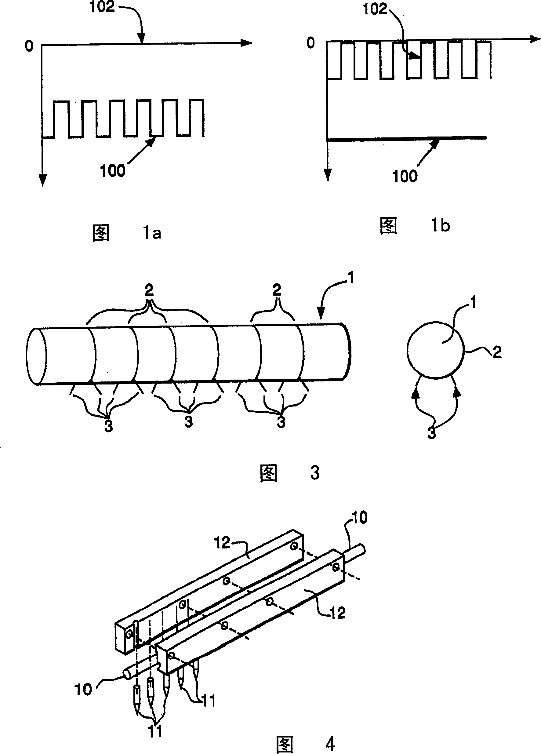
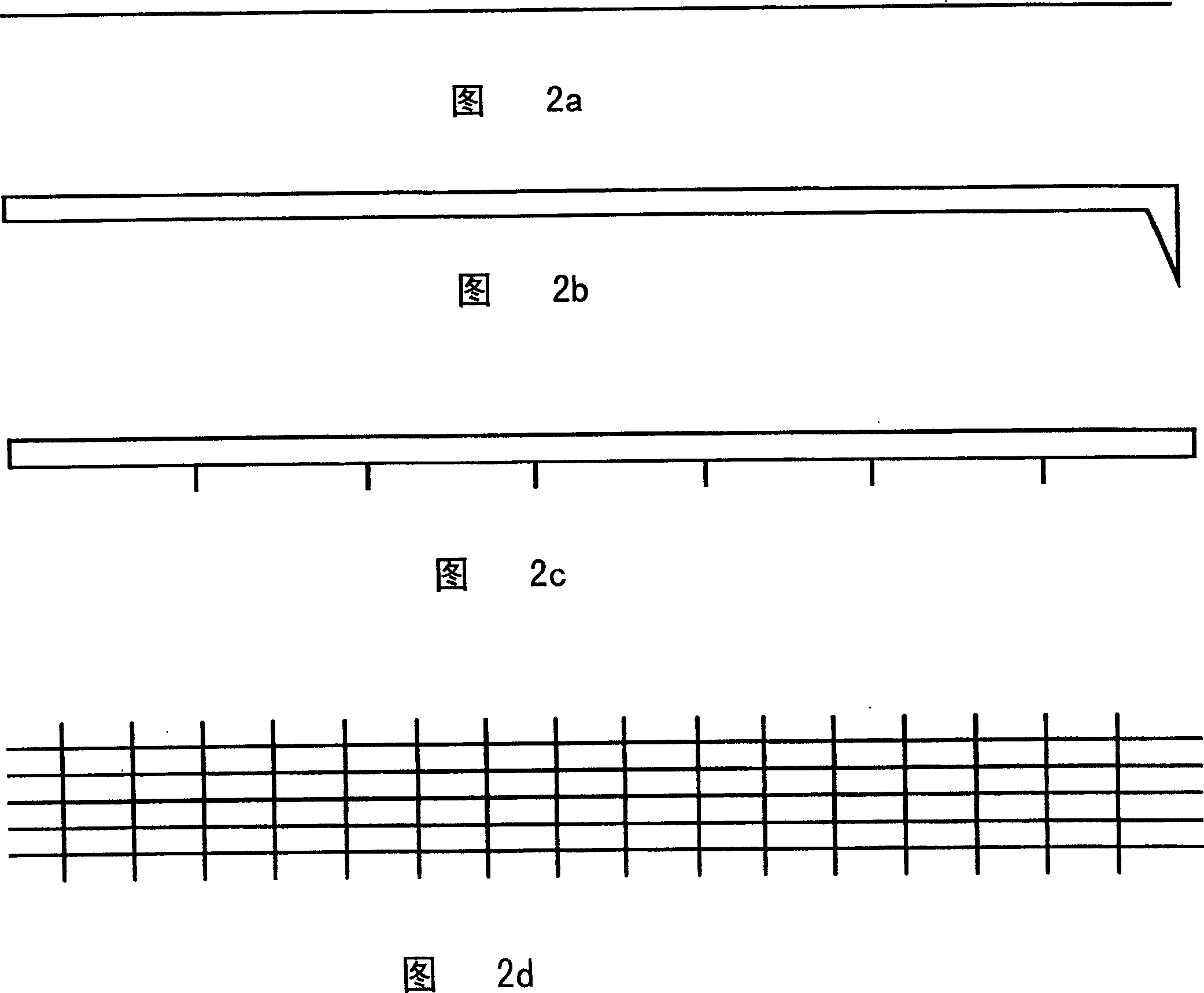
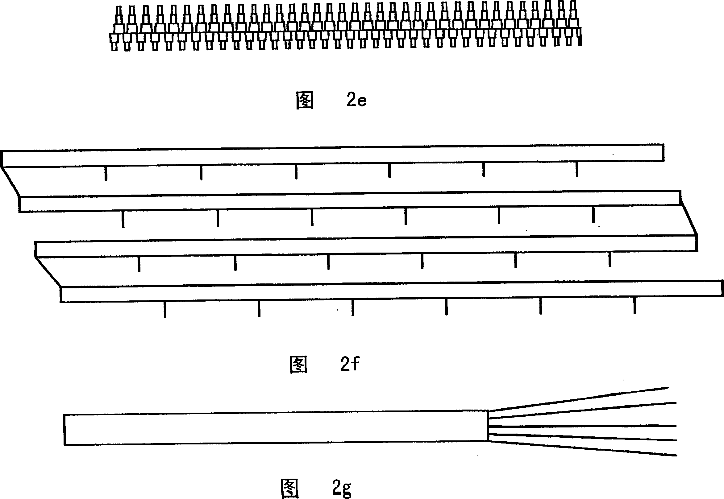
[0091]This example was carried out to investigate the efficiency of the thermal-field emission method of generating electrons. A large 3 mm diameter graphite rod protruding from the rod surface with a 1 mm long machined end served as the cathode, and its geometry was similar to the rod described in Fig. 2i. Each protruding machined end has a tip taper angle of 25 degrees. Resistance heating using AC energy, at 5% H 2 and 95%N 2 The graphite rod is heated to about 400 to 500°C in a gas mixture. A DC voltage source of 5KV was applied between graphite cathodes at 1.5cm intervals and copper sheets as anodes. All endpoints on the graphite are illuminated, indicating that electrons can be generated uniformly from distributed ends of the graphite rod. Without heating the graphite rod, there is no electron emission from the cathode, or a breakdown occurs between one end and the anode sheet. This indicates that the combination of using a cathode with a large number of endpoints an...
PUM
 Abstract
Description
Claims
Application Information
 - R&D Engineer
- R&D Manager
- IP Professional
- Industry Leading Data Capabilities
- Powerful AI technology
- Patent DNA Extraction
Browse by: Latest US Patents, China's latest patents, Technical Efficacy Thesaurus, Application Domain, Technology Topic.
© 2024 PatSnap. All rights reserved.Legal|Privacy policy|Modern Slavery Act Transparency Statement|Sitemap