Omnibearing movable spherical robot

A spherical robot, all-round technology, applied in the direction of manipulators, manufacturing tools, etc., can solve the problems that the stability of motion needs to be improved, the structure of spherical robots is complex, etc., and achieve the effect of simple structure, convenient installation and simple motion mechanism.

Inactive Publication Date: 2007-05-30
BEIHANG UNIV
View PDF5 Cites 0 Cited by
  • Summary
  • Abstract
  • Description
  • Claims
  • Application Information

AI Technical Summary

Problems solved by technology

[0003] The problem of the spherical robot of the above invention or design is that the structure is more complex, and the stability of the movement needs to be improved

Method used


Image

  • Omnibearing movable spherical robot
  • Omnibearing movable spherical robot

Examples


Embodiment Construction

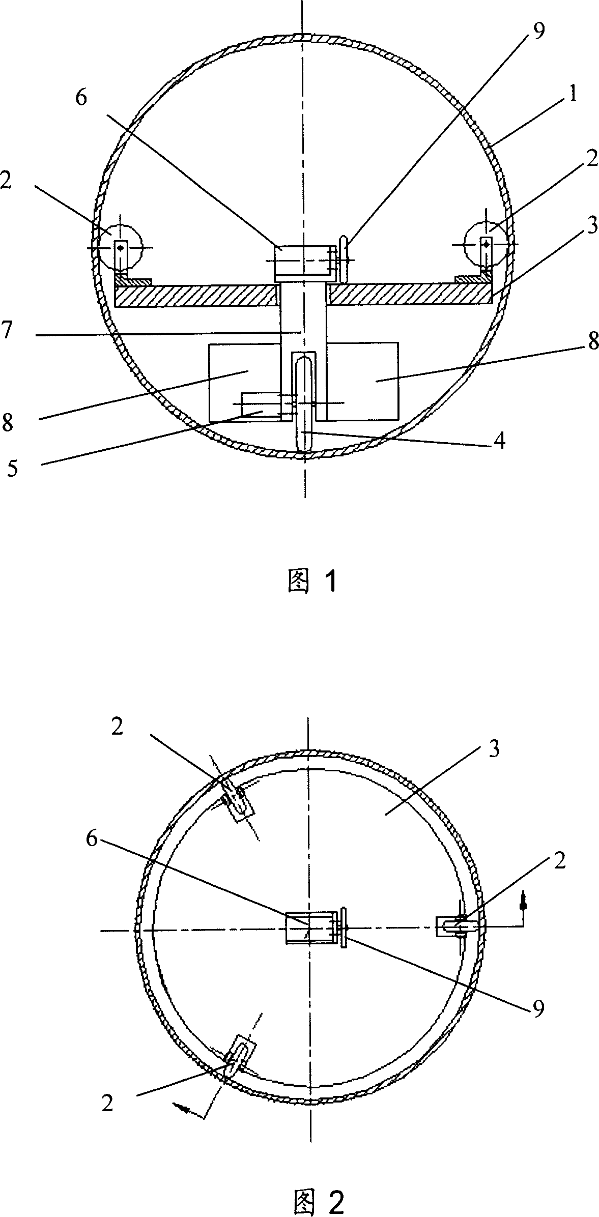
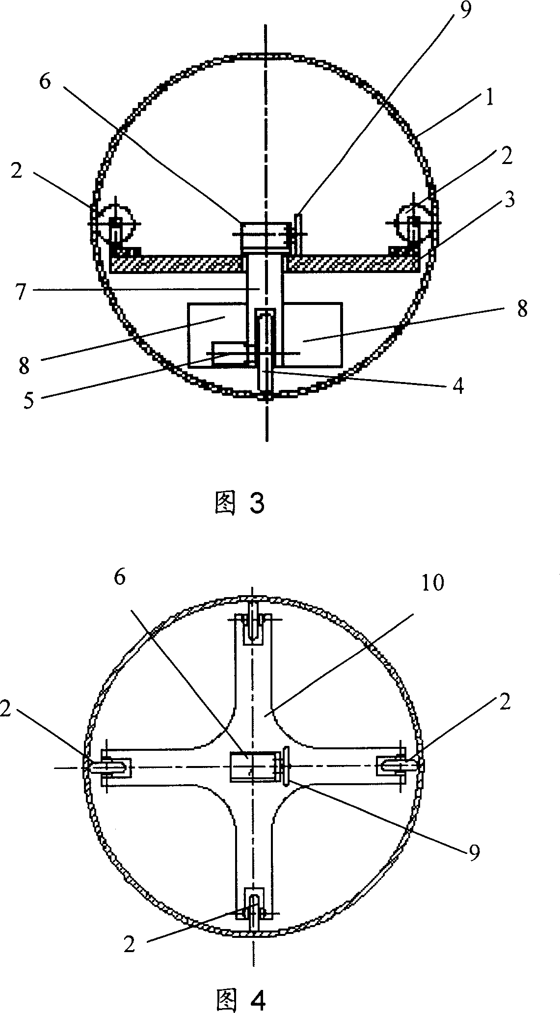
[0013] As shown in Fig. 1 and Fig. 2, one embodiment of the present invention is: there is a motion mechanism 7 supported on the spherical shell by three small wheels 2 inside the spherical shell 1, and the three small wheels 2 can be connected to the On the disc 3, the motion mechanism 7 is composed of two motors 5, 6 and five wheels, three small wheels 2 for support, one large wheel 4 for driving the spherical shell and one wheel connected to the motor 6 9; One of the two motors is used to drive the big wheel 4 in contact with the bottom of the spherical shell, and the other is used to drive the wheel 9 and cause the part of the wheel 4 to rotate relative to the disc. The small wheel 2 is installed on the disc 3 supporting the motion mechanism 7 at 120 degrees. Under the gravity of the internal battery pack and the control system 8 of the motion mechanism 7, the big wheel 4 is in rolling contact with the spherical shell 1. Driven, the big wheel 4 can rotate relative to the s...


PUM


Abstract

An omnibearing spherical robot features that its internal moving mechanism is supported by its spherical casing via at least three single-wheel rolling units and can move relatively to said spherical casing, another single-wheel rolling unit used to make said moving mechanism in rolling contact with said spherical casing is driven by a motor for pushing the spherical casing to do linear movement and by another motor for changing the rolling direction to do omnibeary movement.

Description

technical field [0001] The invention relates to an all-round motion spherical robot system which can be used in the fields of environment detection, star detection and toys. Background technique [0002] Spherical robot or spherical mechanism refers to a general term for a system that installs motion actuators, sensors, and controllers in a spherical housing. Since this type of robot has good dynamic and static balance, it will not be unstable due to collisions. At the same time, since its electromechanical, sensing components and control components are all included in this ball, it has good sealing performance and can drive in sandy, humid and corrosive harsh environments. A.Halme, T.Schonberg and Y.Wang, Motion Control of aSpherical Mobile Robot, 4th IEEE International Workshop on AdvancedMotion Control AMC'96, Mie University, Japan 1996. Introduced a spherical robot designed by AarneHalme of Finland and applied for Patent, the spherical robot uses a wheel rolling in the...

Claims


Application Information

Patent Timeline
Patent Type & Authority Patents(China)
IPC IPC(8): B25J5/00
Inventor 战强藏昊周挺志李珂贾川
Owner BEIHANG UNIV
Why Eureka
Try Eureka