
Sidelight back light module

A backlight module and side-light technology, which is applied in the field of side-light backlight modules, can solve problems affecting the luminance performance of liquid crystal displays, high temperature of lamp tubes, and decrease in brightness of backlight modules.

Inactive Publication Date: 2007-06-13
AU OPTRONICS CORP
View PDF4 Cites 0 Cited by
  • Summary
  • Abstract
  • Description
  • Claims
  • Application Information

AI Technical Summary

Problems solved by technology

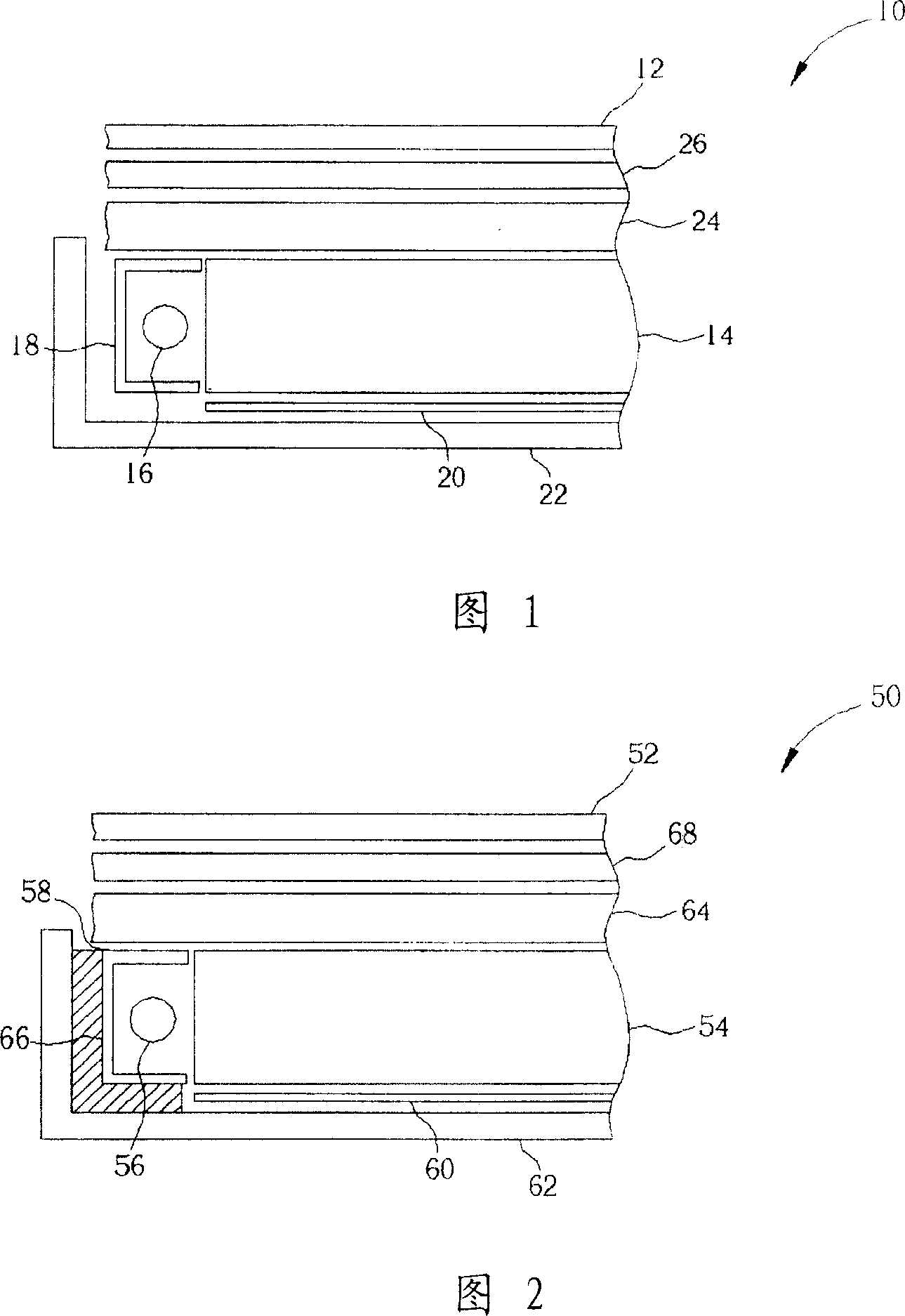
And in order to meet the lightweight requirements of future products such as thinner thickness and smaller volume, the light source generator 16 in the backlight module 10 is often installed in a narrow and small airtight space, so the heat energy generated during operation is often unable to It is emitted smoothly and accumulates continuously. Once the operation time is a little longer, it will easily cause the temperature near the lamp tube to be too high.
However, since cold cathode fluorescent lamps have the best brightness performance when the ambient temperature is 30 to 40°C, high temperature will reduce the brightness of the backlight module and affect the brightness performance of the liquid crystal display.
In addition, excessively high temperature will affect the normal operation of the display panel 12, resulting in a decrease in display quality, and may even greatly reduce the service life of surrounding components.

Method used


Image

  • Sidelight back light module
  • Sidelight back light module
  • Sidelight back light module

Examples


Embodiment Construction

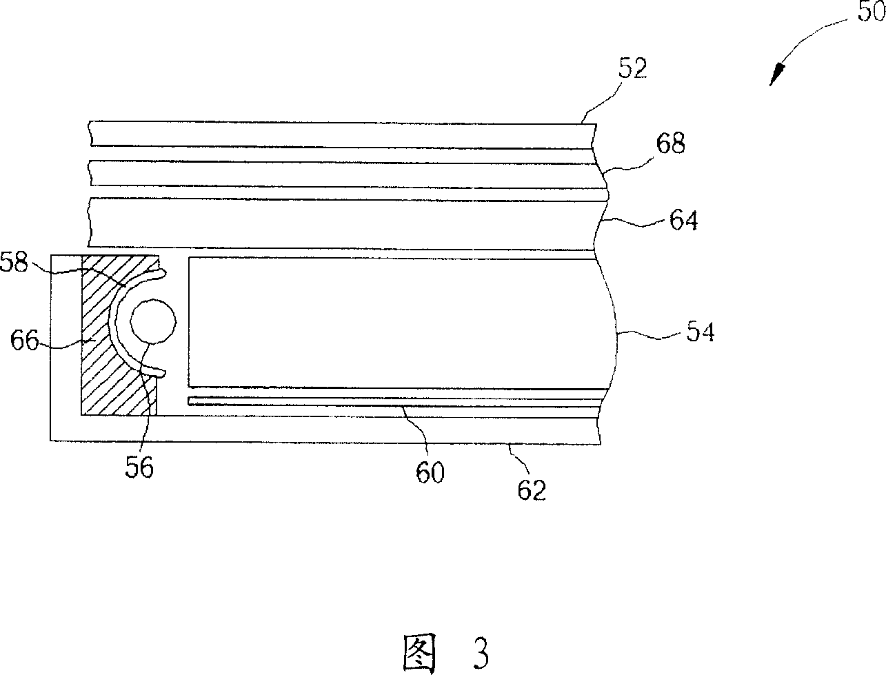
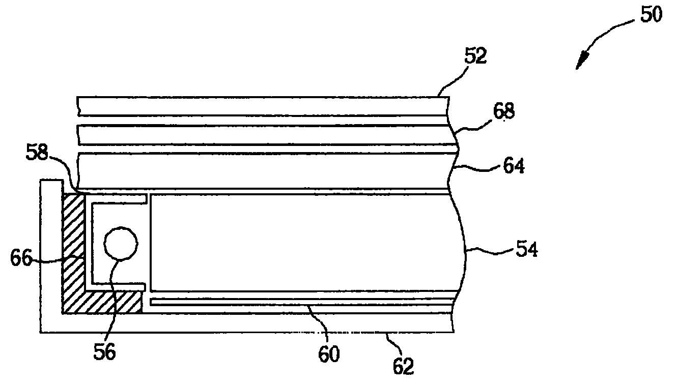
[0010] Please refer to FIG. 2 , which is a schematic cross-sectional view of a first embodiment of an edge-lit backlight module 50 of the present invention. As shown in FIG. 2 , the edge-lit backlight module 50 of the present invention is arranged under a display panel 52, which includes a light guide plate (light guide plate, LGP) 54, arranged under the display panel 52, at least one light source generator ( light source generator) 56 is located on one side of the light guide plate 54, a reflector 58 is located on the other outside of the light source generator 56 relative to the light guide plate 54 and covers the outside of the light source generator 56, a reflective sheet (reflecting sheet ) 60 is arranged under the light guide plate 54 and fixed on a frame 62, a diffusing sheet 64 is arranged between the light guide plate 54 and the display panel 52, and a heat dissipation pad 66 is arranged on the light guide cover 58 and the frame 62 Between them, they are used to trans...


PUM


Abstract

The present invention relates to a sidelight type backlight module, including a light-conducting plate, at least a light source generator placed at side of said light-conducting plate and used for providing a light source and making said light source be entered into said light-conducting plate, at least a reflector placed around said light source generator relatively to the outside of said light-conducting plate and used for reflecting the light produced by said light source generator onto said light-conducting plate, a frame placed in the lower portion of said light-conducting plate and said reflector and used for covering outside of said reflector and a heat-dissipative pad placed between said reflector and said frame.

Description

technical field [0001] The invention relates to an edge light backlight module, in particular to an edge light backlight module with a high cooling effect. Background technique [0002] The backlight module is one of the key components of the liquid crystal display, and has been widely used in digital cameras, digital personal assistants (PDAs), computer monitors and flat-screen TVs. Generally speaking, the backlight module is arranged under a display panel, and has a light source and a light guide plate, which are used to provide a uniformly dispersed light to the display panel, and then control the pixel electrodes on the display panel to form appropriate of the image. Wherein, the backlight module can be divided into a direct type backlight module whose light source is directly below the display panel or an edge light type backlight module whose light source is near the side of the display panel according to the location of the light source. In addition, since the edge-...

Claims


Application Information

Patent Timeline
Patent Type & Authority Patents(China)
IPC IPC(8): G02F1/13357H05B33/00G02F1/1335
Inventor 游川倍郭建宏
Owner AU OPTRONICS CORP
Learn More