
Circuit control protector

A circuit control and protector technology, applied in the direction of protection switch operation/release mechanism, electric heating switch, etc., can solve the problems of incomplete tripping, slow response of linkage stroke, high production cost, etc., so as to reduce manufacturing cost and prolong service life , Make the effect of easy assembly

Inactive Publication Date: 2007-07-25
游聪谋
View PDF9 Cites 0 Cited by
  • Summary
  • Abstract
  • Description
  • Claims
  • Application Information

AI Technical Summary

Problems solved by technology

[0009] The purpose of the present invention is to solve the shortcomings of the traditional power control switch linkage structure, such as complex components, high production cost, indirect linkage relationship, slow response of linkage stroke and many faults in the operation of the power control switch, especially to solve the shortcomings of the traditional power supply When the control switch is overheated due to current overload, it is impossible to trip the power-off (OFF) in real time, or the trip is incomplete, resulting in an overheating state where the circuit continues to flow; When the contact shrapnel cools down, it jumps back to the energized state, and continues to repeatedly energize and power off to form sparks, causing dangerous problems

Method used


Image

  • Circuit control protector
  • Circuit control protector
  • Circuit control protector

Examples


Embodiment Construction

[0035] In order to disclose the purpose, features and effects of the present invention in detail, the present invention will be described in detail through the following preferred specific embodiments, in conjunction with the accompanying drawings:

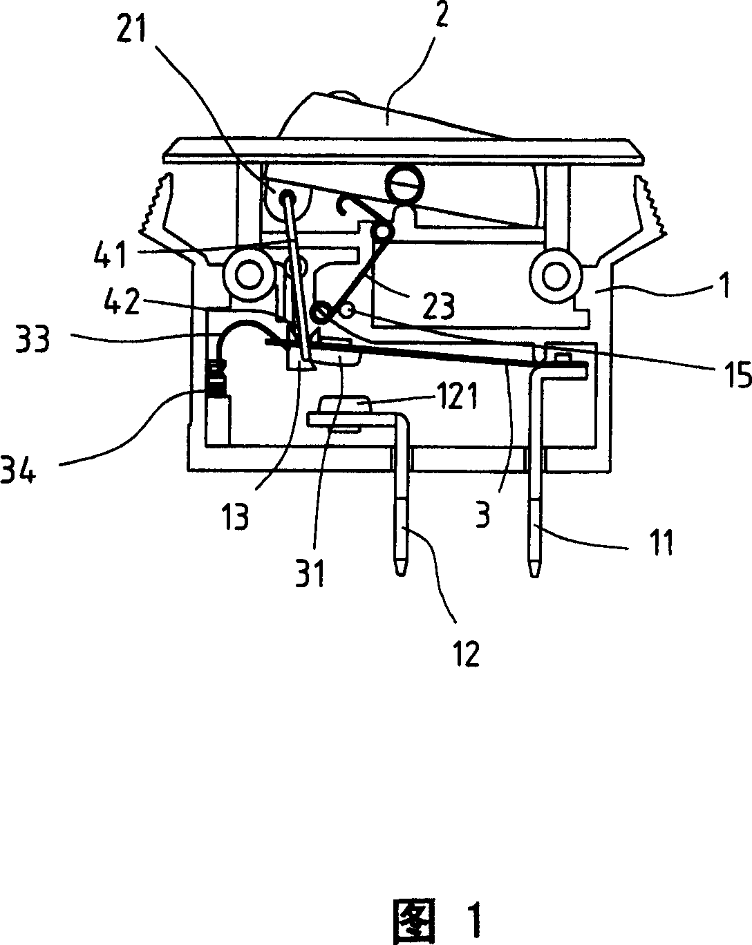
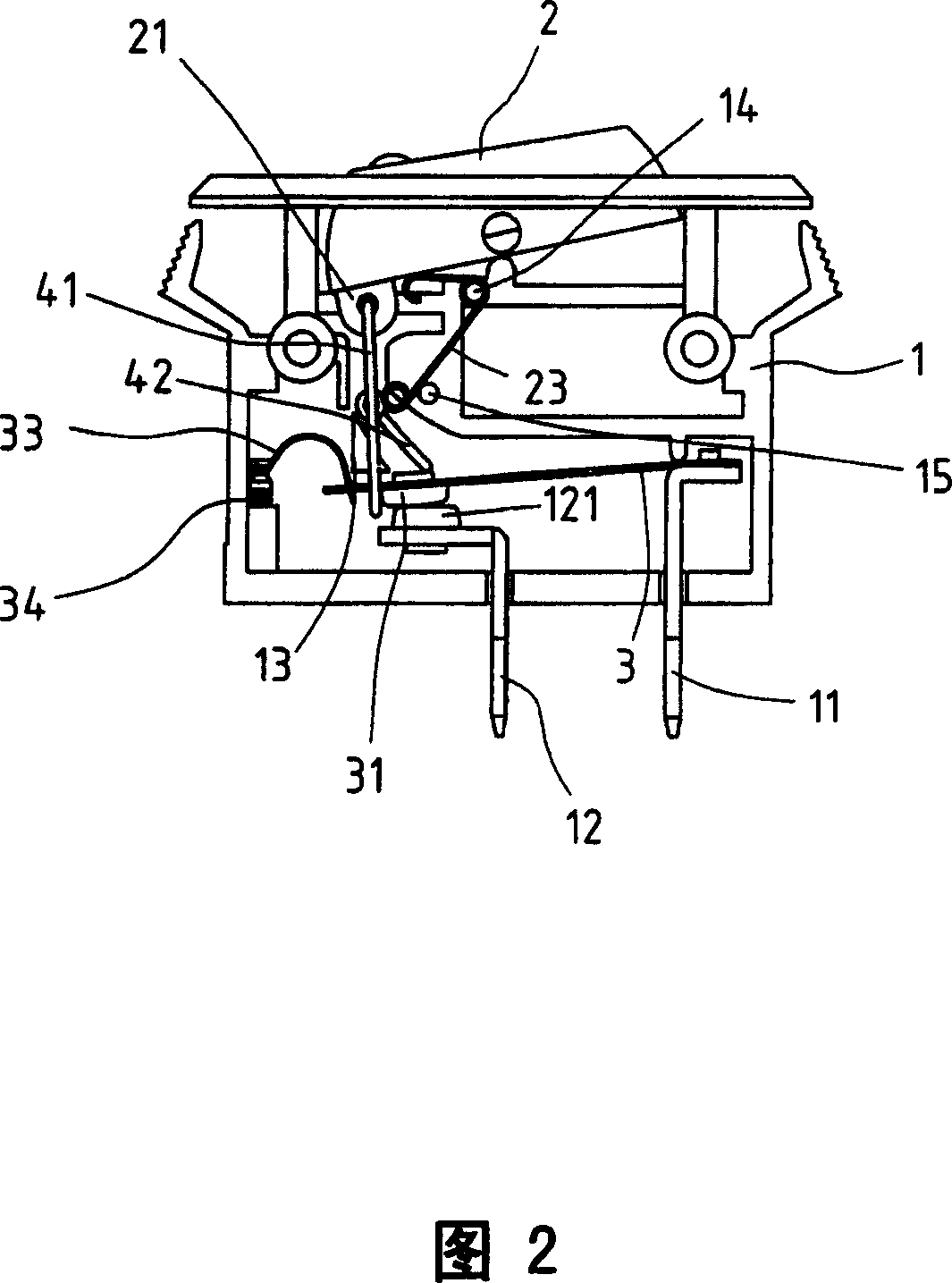
[0036] As shown in Figures 1 and 2, it is a combined cross-sectional view of the embodiment of the present invention, which shows the state of power-off (OFF) and power-on (ON) of the embodiment of the present invention, and Fig. 5 is a partial perspective exploded view of the embodiment of the present invention , which displays the relative combination state of the button, the control lever set and the contact piece; a circuit control protector of the present invention mainly includes a box body 1, a button 2, a contact piece 3, and a control lever set 4 ;in,

[0037] The box body 1 is hollow, with an opening above it, and at least two contact terminals are arranged on the bottom surface of the box body 1. In this embodiment, the...


PUM


Abstract

The present invention provides one kind of circuit control protector. The button combination is connected with one control rod assembly comprising one pull rod and one push rod with one contact chip in between. During acting, the button drives the control rod assembly, the pull rod pulls the contact chip or the push rod pushes the contact chip and the contact chip is made to jump and bend to sides for power on or off. When the button is in the on position, the push rod rotates by certain angle and its end contacts with the contact chip obliquely to form one acute angle without blocking the deforming displacement of the contact chip. In case of overcurrent, the contact chip is heated to deform and jump inversely without limitation of the push rod to reach power off state for safety.

Description

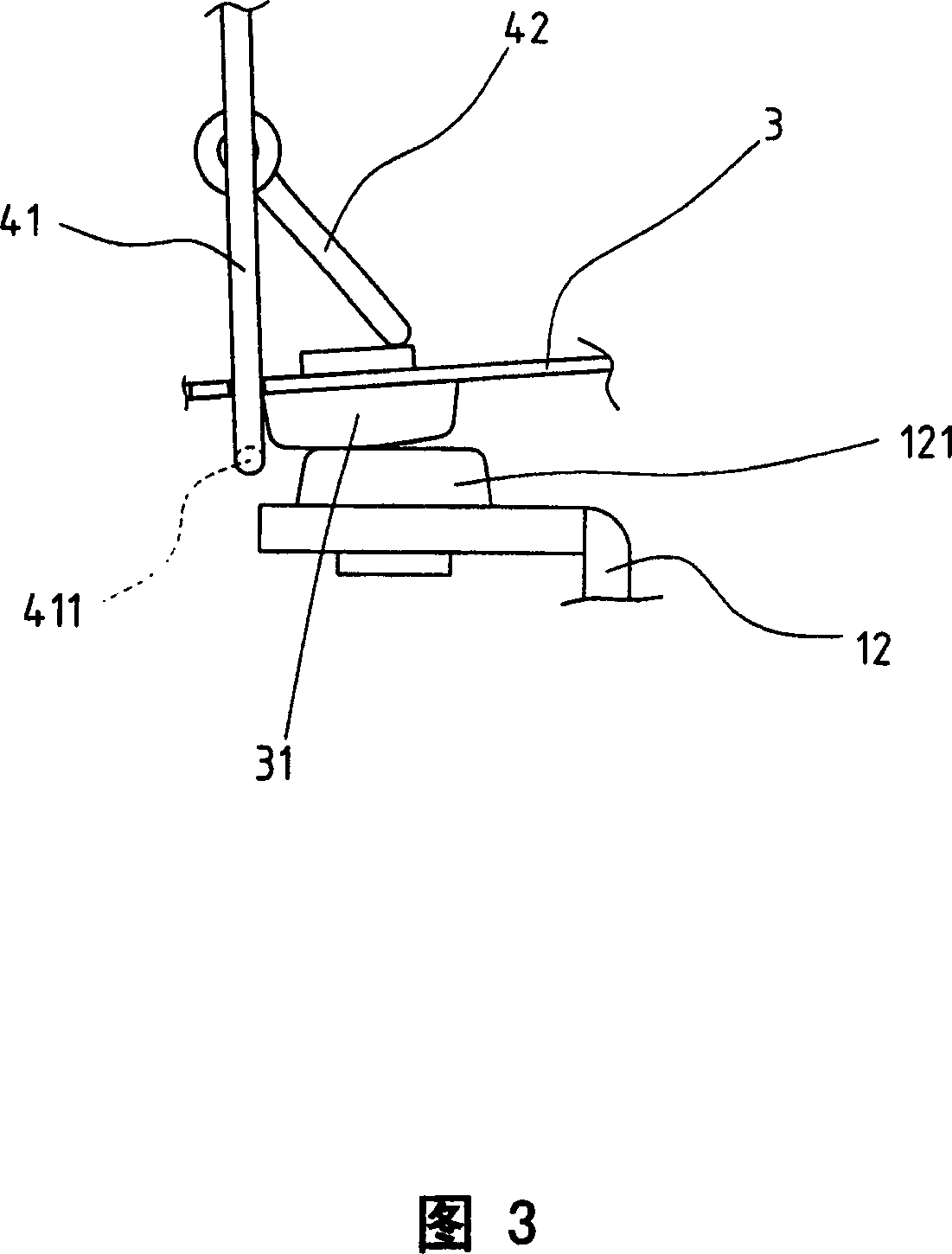
technical field [0001] The invention relates to a circuit control protector, which utilizes a button to link a control rod group, by pressing the button to swing, the control rod group moves synchronously, and the push-pull contact piece jumps, so that the circuit loop is energized (ON) or disconnected. Power (OFF) state; in the state of power (ON), the end of the push rod of the control rod group is in oblique contact with the surface of the contact piece, which will not block the deformation and displacement of the contact piece to the direction of the push rod. When the current is overloaded When the contact piece is deformed by heat and bounces back, it is not restricted by the push rod of the control rod group, and the contact piece can be deformed freely and jump off smoothly, forming a complete power-off (OFF) state of the circuit loop. Background technique [0002] The operation of the power control switch is mainly to perform two action strokes of power-on (ON) and ...

Claims


Application Information

Patent Timeline
Patent Type & Authority Patents(China)
IPC IPC(8): H01H77/04H01H71/52H01H71/58H01H71/16
Inventor 游聪谋
Owner 游聪谋
Learn More