
Cold-rolling mill and its rolling method

A technology of cold rolling mills and rolling mills, which is applied in the direction of rolling mill control devices, metal rolling, metal rolling, etc., and can solve problems such as strip shape deterioration

Inactive Publication Date: 2002-03-20
HITACHI LTD
View PDF5 Cites 12 Cited by
  • Summary
  • Abstract
  • Description
  • Claims
  • Application Information

AI Technical Summary

Problems solved by technology

In this case, if the thermal crowning is controlled by a roll bender, the above-mentioned body crowning will change and the shape of the strip will be deteriorated

Method used


Image

  • Cold-rolling mill and its rolling method
  • Cold-rolling mill and its rolling method
  • Cold-rolling mill and its rolling method

Examples


Embodiment Construction

[0101] Several embodiments of the present invention will be described in detail below with reference to the accompanying drawings.

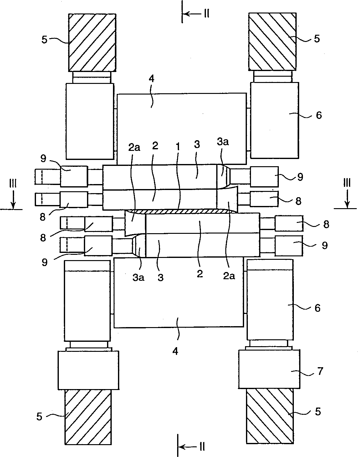
[0102] figure 1 A vertical front sectional view of a six-high rolling mill (cold rolling mill) showing one embodiment of the present invention.

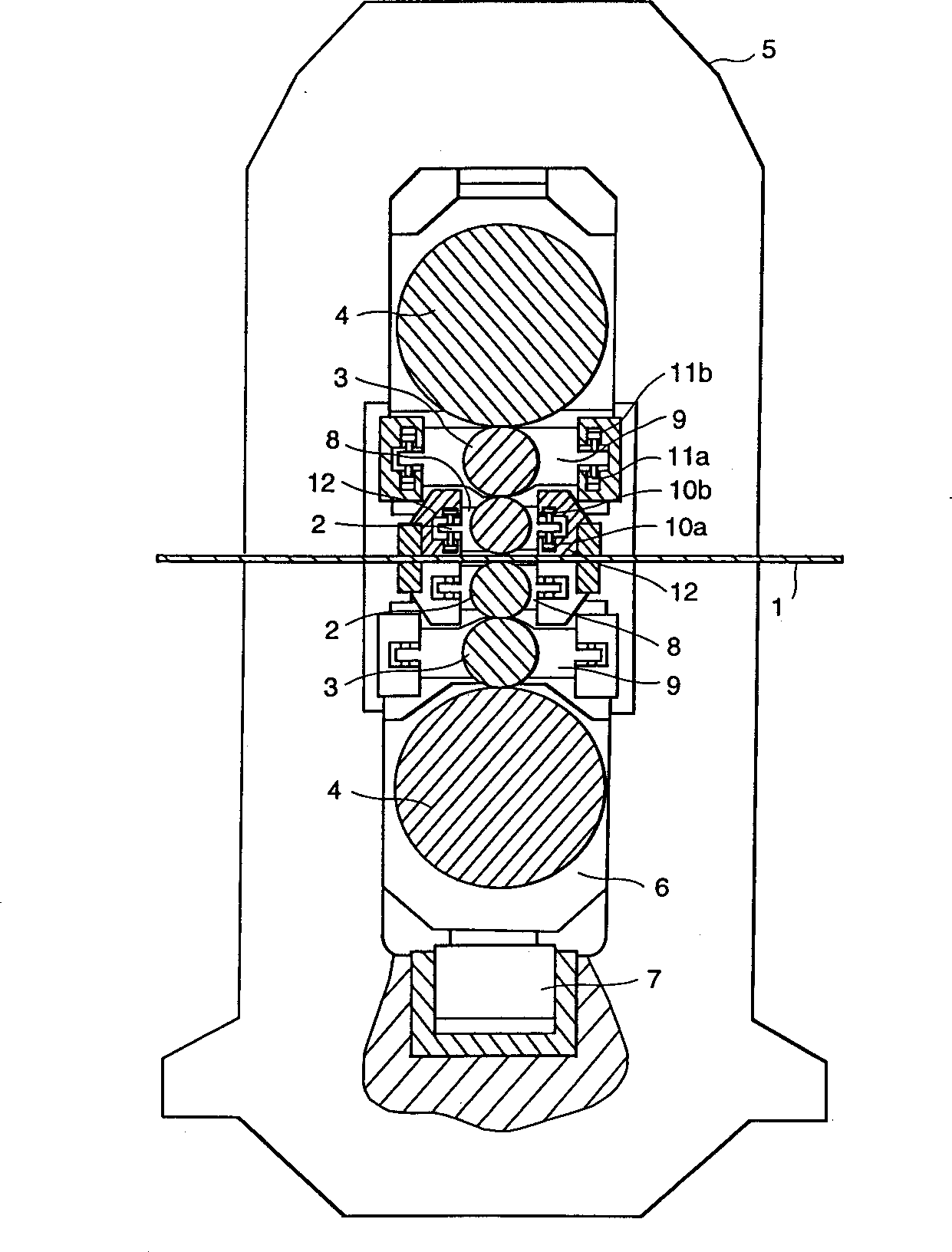
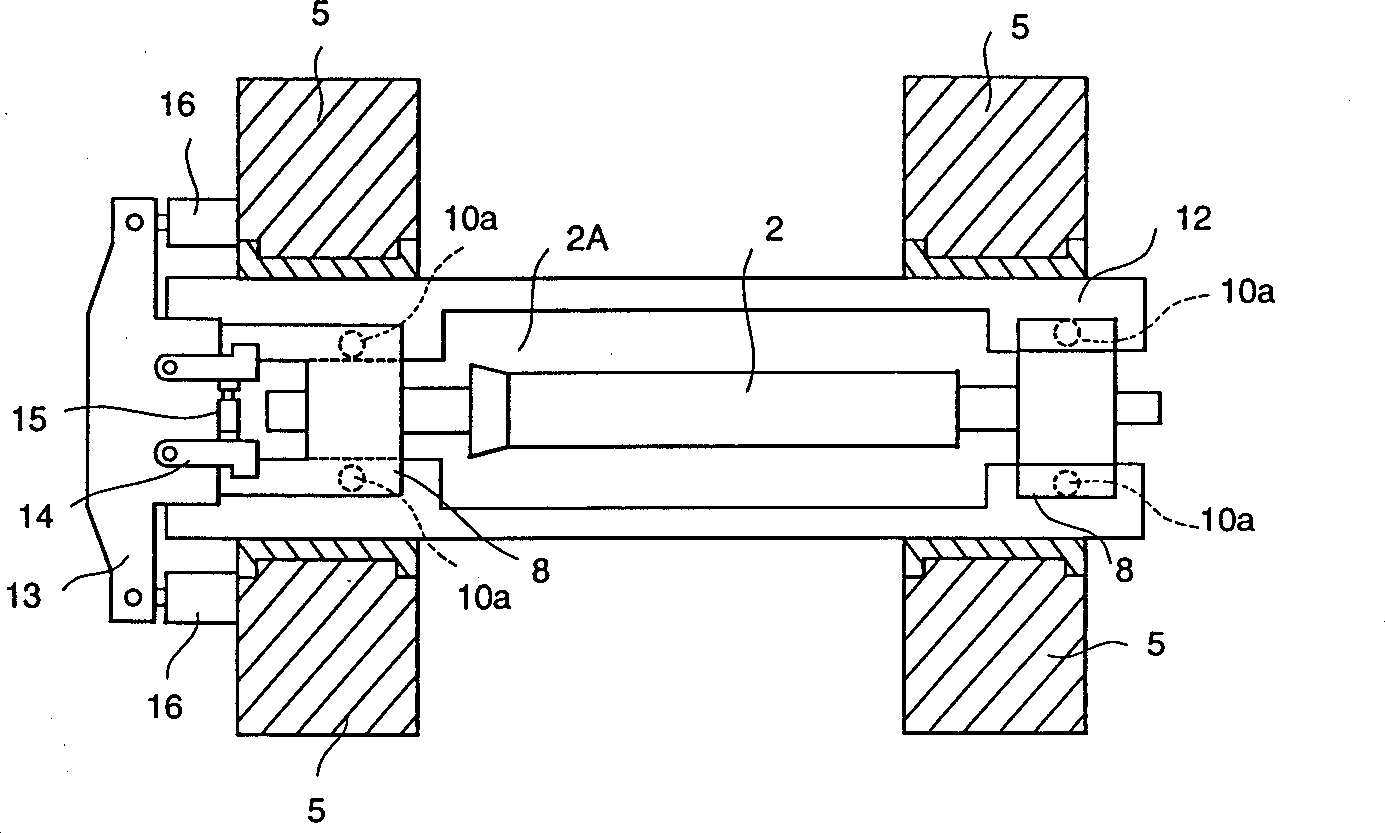
[0103] figure 2 with image 3 respectively show along the figure 1 Cross-sectional views of lines II-II and III-III of the embodiment.

[0104] exist Figure 1~3 Among them, the six-high rolling mill has a work roll 2 that directly contacts the strip 1 and rolls the strip 1, an intermediate roll 3 that contacts the work roll 2, a backup roll 4 that contacts the intermediate roll 3, and a back-up roll 4. Bearing box 8, and the frame 5 supporting each roll by bearing box 8. The hydraulic jack 7 positioned on the bottom of the frame 5 makes the bearing housing 6 of the support roll 4 rise and fall to adjust the pressure applied to the strip 1 . The work roll 2 and the intermediate roll 3 are respec...


PUM


Abstract

A 6-high rolling mill in accordance with the present invention wherein each of the working rolls 2 which are equipped with a shifting means has a locally gradually-thickened-toward-end part (or a local concave crown 2a) on one end of the roll, the working rolls 2 are disposed so that the locally gradually-thickened-toward-end parts of the working rolls 2 may be vertically symmetrically with a point, a decremental bender 10b which works to narrow the gap between the working rolls is provided as a first shape control means, both the local concave crowns 2a and the roll bender 10b are used to control thermal crowns, and an incremental bender 11a which controls bending of the intermediate rolls 3 is provided as a second shape control means which controls so that the center of a strip may have a concave crown.

Description

technical field [0001] The present invention relates to a cold rolling mill and a rolling method thereof, more particularly, to a cold rolling mill of four or more rolls used in reversing cold rolling equipment, aluminum rolling equipment or copper rolling equipment and the use of the above Rolling method in cold rolling mill. Background technique [0002] When rolling the steel strip, due to the temperature change along the axial direction of each work roll, the thermal expansion of the rolls is different, which will cause the diameter of the roll to change along the width direction of the roll. This phenomenon is called thermal humping (or humping). In other words, this is due to the fact that the heat generated during the rolling process and the friction between the roll and the strip to be rolled will cause the part of the roll in contact with the hot strip to be heated much more severely than other parts. When the above-mentioned amount of thermal swelling is large, th...

Claims


Application Information

Patent Timeline
Patent Type & Authority Applications(China)
IPC IPC(8): B21B1/22B21B13/02B21B13/14B21B27/02B21B29/00B21B31/18B21B37/00B21B37/28B21B37/38B21B37/40B21B37/42B21C51/00
CPCB21B2013/025B21B13/023B21B37/42B21B31/185B21B13/142B21B37/38B21B2027/022B21B37/40B21B37/28B21B27/02B21B2013/028B21B37/00
Inventor 小林裕次郎梶原利幸乳井辰彰菊池有二芳村泰嗣山田繁一
Owner HITACHI LTD
Learn More