Tester and testing method, and testing unit

A detection device and a detection component technology, which can be applied to measurement devices, devices that automatically compare measured values ​​with reference values, and measurement electronics, etc., and can solve the problems of increasing surface mounting density and limited application range.

Inactive Publication Date: 2002-07-10
OHT
View PDF0 Cites 17 Cited by
  • Summary
  • Abstract
  • Description
  • Claims
  • Application Information

AI Technical Summary

Problems solved by technology

[0007] However, the existing non-contact detection method also needs to be in contact with the lead pin at one end, so it is not a complete non-contact detection technology. In today's increasingly high-density conductive patterns, its scope of application is quite limited
[0008] Moreover, in general, one end of the conductive pattern needs to be provided with a pad (pad) for contact with the lead pin, and the installation of an unnecessary pad will increase the surface mounting density.

Method used


Image

  • Tester and testing method, and testing unit
  • Tester and testing method, and testing unit
  • Tester and testing method, and testing unit

Examples


Embodiment Construction

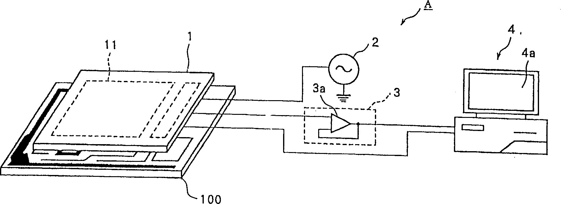
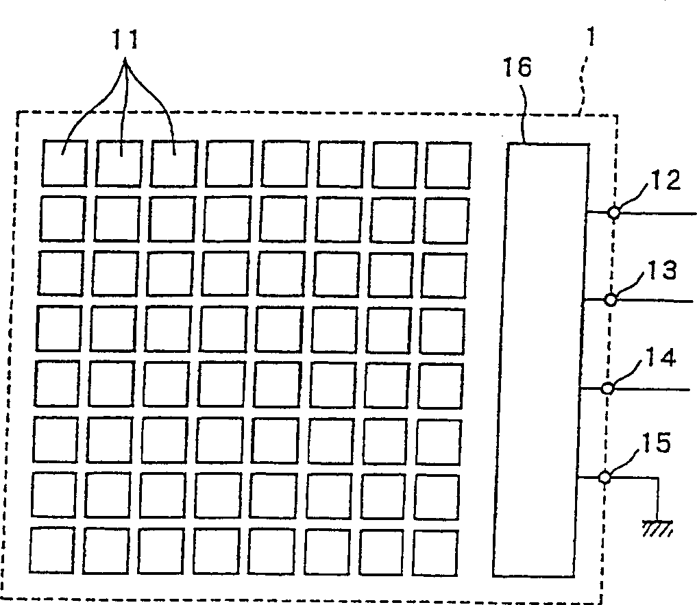
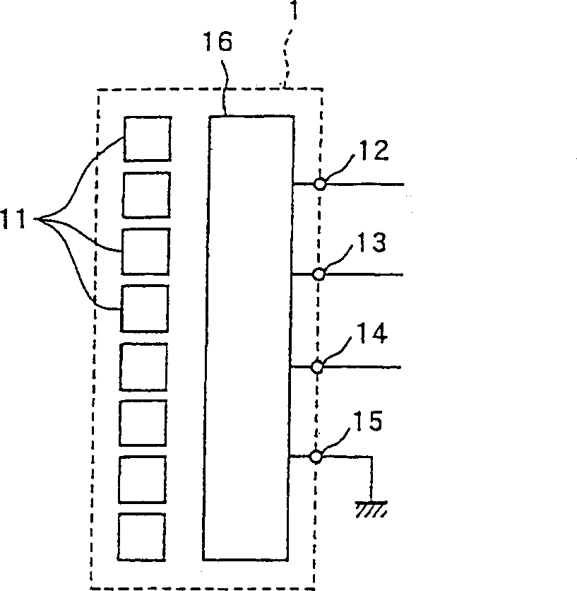
[0035] figure 1 It is a schematic diagram showing the configuration of a detection device A for detecting a conductive pattern on a circuit board 100 as a first embodiment of the present invention, figure 2 It is a schematic diagram showing the structure of the detection component 1 therein.

[0036]

[0037] The detection device A has a detection component 1, a signal source 2 for supplying a detection signal to the detection component 1, a processing circuit 3 for processing an output signal given by the detection component 1, and a control for the detection component 1, and can be based on The computer 4 is used to determine whether the conductive pattern on the circuit board 100 is disconnected, short-circuited, etc. by the output signal given by the processing circuit 3 .

[0038] The detection assembly 1 has several units 11 which are isolated from each other, the input terminal 12 which inputs the detection signal given by the signal source 2, the output terminal 13...


PUM


Abstract

The present invention provides an inspection apparatus, an inspection method and an inspection unit therefor capable of inspecting a conductive pattern in a complete non-contact manner. In the method for inspecting a conductive pattern of a circuit board in a complete non-contact manner, a plurality of electrically conductive cells 11 are arranged along the conductive pattern of the circuit board 100 with leaving a space therebetween. An inspection signal having temporal variations is supplied to at least one of the cells in the conductive pattern without using any pin. An output signal appearing at another at least one of the cells through the conductive pattern in response to the applied inspection signal is detected. The conductive pattern is inspected based on the detected output signal.

Description

technical field [0001] The invention relates to the technique of detecting the conductive pattern on the circuit substrate. Background technique [0002] In the manufacturing process of the circuit substrate, after the conductive pattern is arranged on the substrate, it is necessary to detect whether the conductive pattern has a disconnection or a short circuit fault. [0003] At present, as this type of detection technology, it is usually to make the two ends of the conductive pattern contact with the lead pins, and supply electrical signals from the lead pins at one end to the conductive pattern, and receive them from the lead pins at the other end. In the way of electrical signals, contact detection techniques such as conduction detection and the like are implemented on conductive patterns. [0004] However, in recent years, with the increasing density of conductive patterns, it has become more and more difficult to realize the detection method of contacting each conduct...

Claims


Application Information

Patent Timeline
Patent Type & Authority Applications(China)
IPC IPC(8): G01R31/02G01R31/312
CPCG01R31/312G01R17/02G01R31/318392
Inventor 石冈圣悟山冈秀嗣
Owner OHT
Why Eureka
Try Eureka