Wrist-wearing electronic device
An electronic device, wrist-worn technology, applied in electronic timers, electronic timer structural details, telephone structure and other directions, can solve the problems of inconvenient detachment, difficult wearing, and difficult to open, etc., and achieve the effect of easy detachment
- Summary
- Abstract
- Description
- Claims
- Application Information
AI Technical Summary
Problems solved by technology
Method used
Image

Examples
Embodiment 1
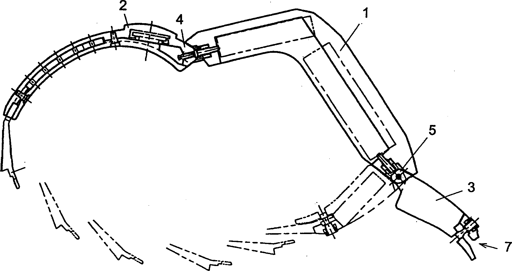
[0050] figure 1 is a cross-sectional view of the wrist-worn electronic device according to Embodiment 1 of the present invention. As shown in the figure, the wrist-worn electronic device is composed of a main body 1 bent substantially in an L shape and overlapping straps 2 and 3 made of hard materials. Although in the figure, two lapping straps 2 and 3 are connected to both sides of the main body 1 by hinges 4 and 5, the configuration may also be a single lapping strap or several lapping straps connected to each other. One side of the front end of the overlapping strap 2 is provided with an inserting portion 6, which is joined together by being inserted into the inserted portion 7 on the other side of the overlapping strap 3 which can rotate around the pivot. Thereby, the wrist-worn electronic device can be fixed on the wrist.
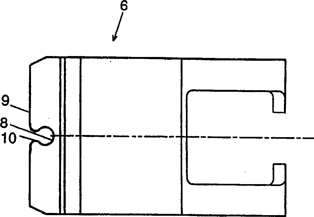
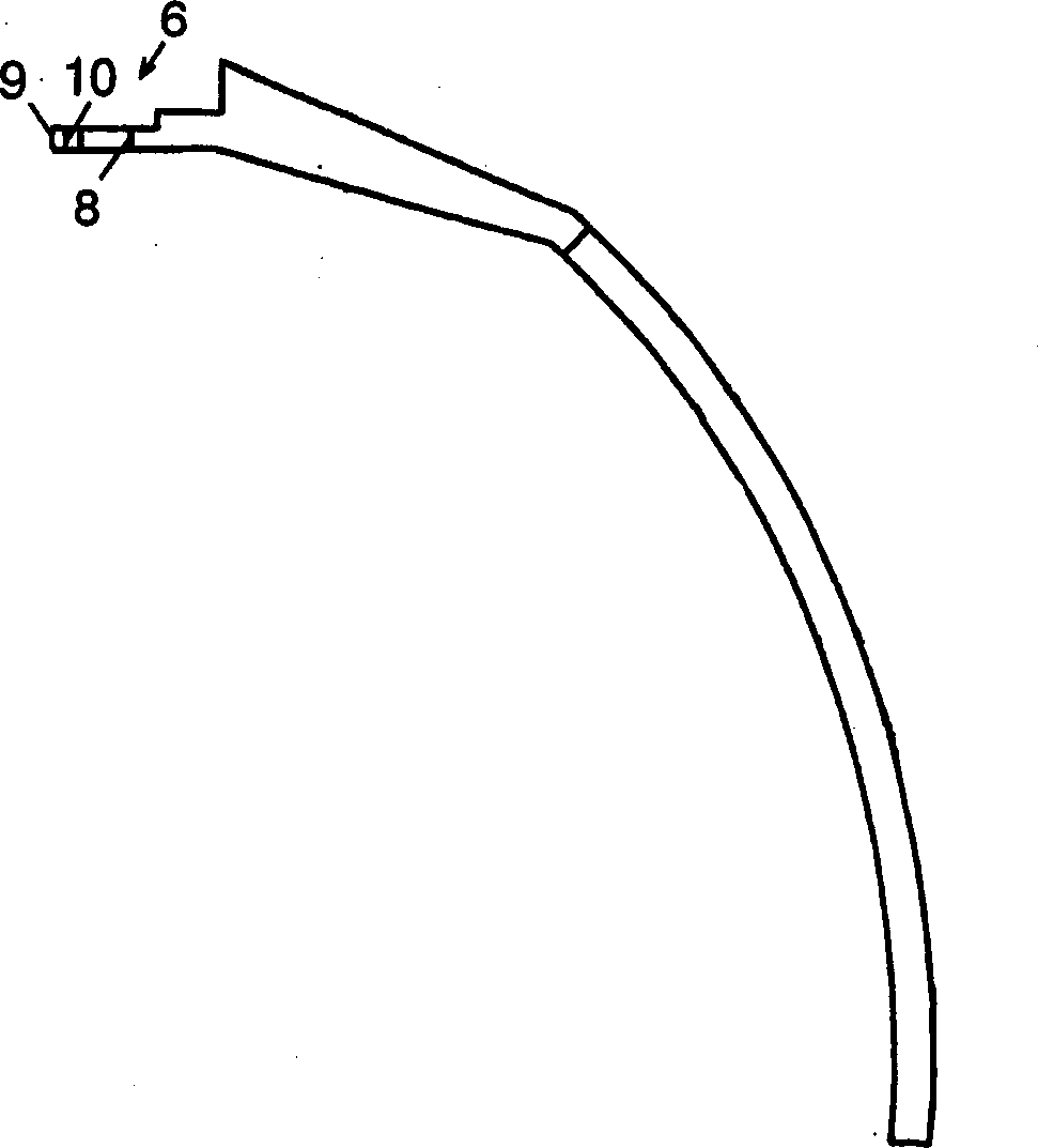
[0051] Figure 2A and 2B are the front and side views of the insert. The insertion portion 6 is formed in a planar shape and has a small hole 8 ...
Embodiment 2
[0062] Fig. 6 shows a wrist-worn electronic device and a hinge according to Embodiment 2 of the present invention. Figure 6A is a side view of the entire electronic device, while Figure 6B It is a front view of the hinge part. Figure 6A The illustrated wrist-worn electronic device 30 consists of a main body 31 and two straps 32 and 33 . In the figure, the overlapping strap 32 on the left is in a closed state, while the overlapping strap 33 on the right is in an open state. The main body 31 is hinged to the straps 32 and 33 . Holes 36 and 37 pass diametrically through the surfaces of the hinge parts 34 and 35 on the side of the straps 32 and 33 .
[0063] Holes 40 and 41 are also provided in hinge members 38 and 39 opposite holes 36 and 37 . The left and right hinges are constructed in the same way, so for convenience only the left hinge is covered here. The hole 36 of the hinge member 34 houses a locking pin 42 which is spring-biased toward the opening side. As the st...
Embodiment 3
[0069] Figure 8 is a cross-sectional view of the wrist-worn electronic device according to Embodiment 3.
[0070] Usually, the hinge structure has two hinge parts that are pivotable relative to each other. As the pivotable structure, there are a structure in which a recessed portion and a protruding portion cooperate and a sliding structure consisting of a shaft portion in the longitudinal pivot direction and a cover portion covering the shaft portion. According to the invention, the hinges used are at least of the latter construction. In addition, although the hinge 50 seems to be separated from the main body 51 of the wrist-worn electronic device and can be swung according to the drawings, this is because what is shown is a sectional view of the shaft portion, and the hinge 50 must be connected to the main body 51 and overlap. with connected.
[0071] The lapping strap 52 is separable up and down, and has a covering portion 54 for covering the shaft portion 53 along the ...
PUM
 Abstract
Description
Claims
Application Information
 - R&D Engineer
- R&D Manager
- IP Professional
- Industry Leading Data Capabilities
- Powerful AI technology
- Patent DNA Extraction
Browse by: Latest US Patents, China's latest patents, Technical Efficacy Thesaurus, Application Domain, Technology Topic.
© 2024 PatSnap. All rights reserved.Legal|Privacy policy|Modern Slavery Act Transparency Statement|Sitemap