Dome shaped contact plate having good knocking sense and thin sheet installed with contact plate

A contact and sheet technology, applied in the direction of quick-action devices, emergency protection devices, electrical components, etc., can solve the problems of poor knock feeling, small movement, and inability to recover by itself.

Inactive Publication Date: 2002-08-28
ALPS ALPINE CO LTD
View PDF0 Cites 4 Cited by
  • Summary
  • Abstract
  • Description
  • Claims
  • Application Information

AI Technical Summary

Problems solved by technology

[0009] However, when the structure of the movable contact 51 of the above-mentioned prior art is used for a flat circuit board 55 or the like, when the dome portion 51b of the movable contact 51 is reversed, the contact portion 51 and the contact portion 51 are separated from each other. The distance (move amount) L2 of the central fixed contact 56 is smaller than L1, so as Figure 11 As shown in B in , when the movable contact 51 is turned over, t

Method used


Image

  • Dome shaped contact plate having good knocking sense and thin sheet installed with contact plate
  • Dome shaped contact plate having good knocking sense and thin sheet installed with contact plate
  • Dome shaped contact plate having good knocking sense and thin sheet installed with contact plate

Examples


Embodiment Construction

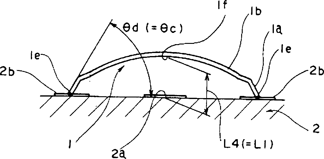
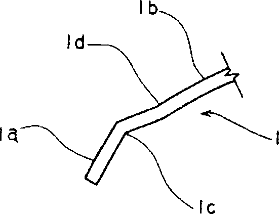
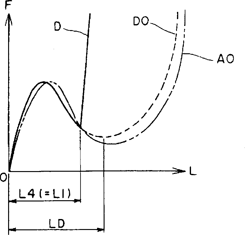
[0030] Below, an embodiment of the present invention is shown in Figure 1 to Figure 3 . figure 1 It is a sectional view showing the relationship between the movable contact and the fixed contact, figure 2 It is a partial sectional view showing the connection part of a side edge part and a dome part, image 3 It is an explanatory diagram showing the relationship between the operating force and the movement amount of the movable contact.

[0031] In the figure, the movable contact 1 is formed in a disc shape from a thin metal plate. The movable contact 1 is formed by a side edge portion 1a rising upward at a predetermined angle from the outer circumference of the disk portion toward the center of the disk portion, and a reversible dome portion 1b connected to the side edge portion 1a. The middle of the side edge portion 1a and the dome portion 1b are connected in a plurality of steps via a plurality of bending portions 1c, 1d (two in this embodiment).

[0032] The circuit...


PUM


Abstract

The present invention provides a structure of a movable contact that can have a good knock feeling even when it is used for a flat circuit board, and will not cause a badly restored movable contact after being turned over. The contact structure consists of a disk portion in which the center of the thin metal plate is bulged in one direction into a dome shape, and has a predetermined angle from the outer peripheral portion of the disk portion to the center portion of the disk portion. The side edge portion 1a is connected to the side edge portion 1a and the dome portion 1b which can be turned over repeatedly is connected, and the middle of the connection portion between the side edge portion 1a and the dome portion 1b is formed into a multi-step shape through a plurality of bending portions 1c and 1d.

Description

technical field [0001] The present invention relates to a contact plate used as a movable contact of a push button switch, and more particularly to a contact plate punched into a dome-shaped disk, a sheet with the contact plate and a switch device using the same. Background technique [0002] In the prior art, as a structure of a contact plate for a movable contact of a push button switch, such as Figure 8 to Figure 12 The structures shown are well known. Figure 8 to Figure 10 It is a sectional view showing the relationship between the movable contact and the fixed contact, Figure 11 with Figure 12 It is an explanatory diagram showing the relationship between the operating force and the movement amount of the movable contact. [0003] Figure 8 It shows the state in which the movable contact 51 of a dome-shaped disc shape formed by swelling out of a thin metal plate is placed on the central fixed contact 53 and the peripheral fixed contacts 54. The central fixed conta...

Claims


Application Information

Patent Timeline
IPC IPC(8): H01H13/48H01H5/30H01H13/52
CPCH01H5/30H01H13/48H01H2227/026H01H13/52
Inventor 山形武夫岛谷胜明
Owner ALPS ALPINE CO LTD
Why Eureka
Try Eureka