
Adaptive antenna receiving unit

An adaptive antenna and receiving device technology, which is applied in antennas, selection devices, diversity/multi-antenna systems, etc., can solve the problem of reduced beam band interference suppression characteristics and achieve good interference suppression characteristics

Inactive Publication Date: 2002-09-18
NEC CORP
View PDF1 Cites 6 Cited by
  • Summary
  • Abstract
  • Description
  • Claims
  • Application Information

AI Technical Summary

Problems solved by technology

In addition, the interference suppression characteristics outside the beam band are also greatly reduced

Method used

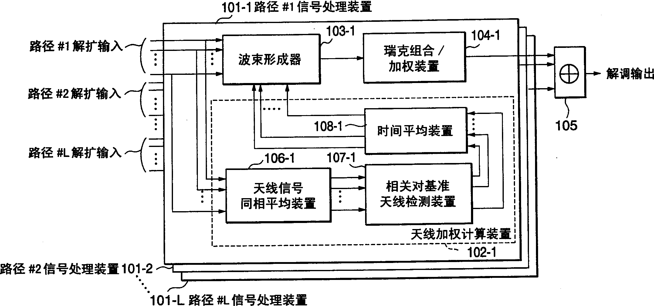

Image

  • Adaptive antenna receiving unit
  • Adaptive antenna receiving unit
  • Adaptive antenna receiving unit

Examples


no. 1 example

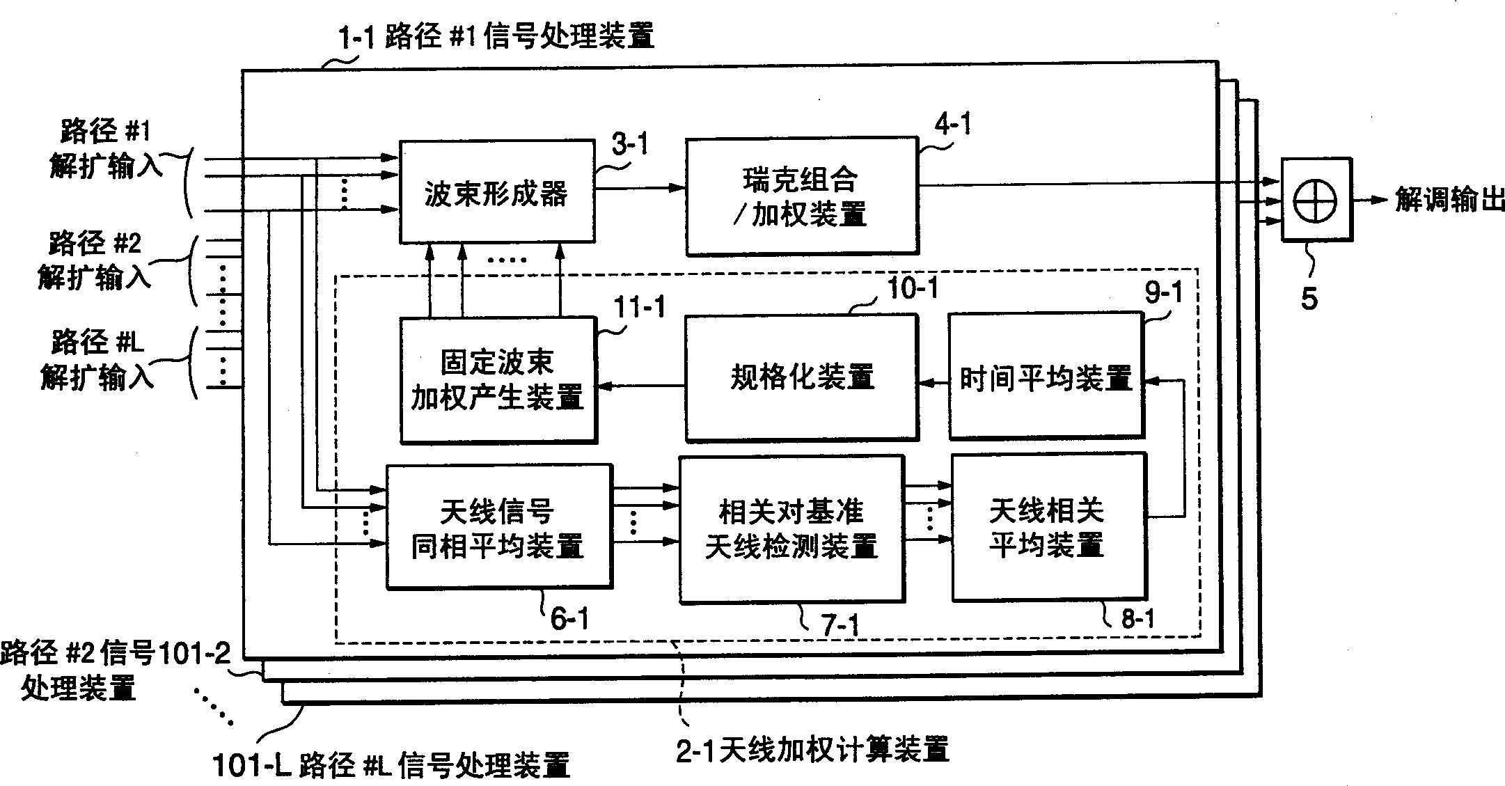
[0054] The following reference figure 2 A first embodiment of the present invention will be described. A first adaptive antenna receiving apparatus according to the present invention has path signal processing means 1-1 to 1-L for receiving and demodulating CDMA signals corresponding to multipath transmission paths in a mobile communication environment. That is, when there are L (L is a positive integer) multipath transmission paths, L path signal processing devices are configured.

[0055] This adaptive antenna receiving device has path signal processing devices 1 - 1 to 1 -L and a combiner 5 .

[0056] The path signal processing means 1-1 to 1-L respectively have antenna weight calculation means 2-1 to 2-L, beamformers 3-1 to 3-L, and rake combining / weighting means 4-1 to 4-L . The path signal processing device 1-1 corresponding to path #1 will be described below. This explanation can also be applied to the path signal processing devices 1-2 to 1-L.

[0057] Antenna we...

no. 2 example

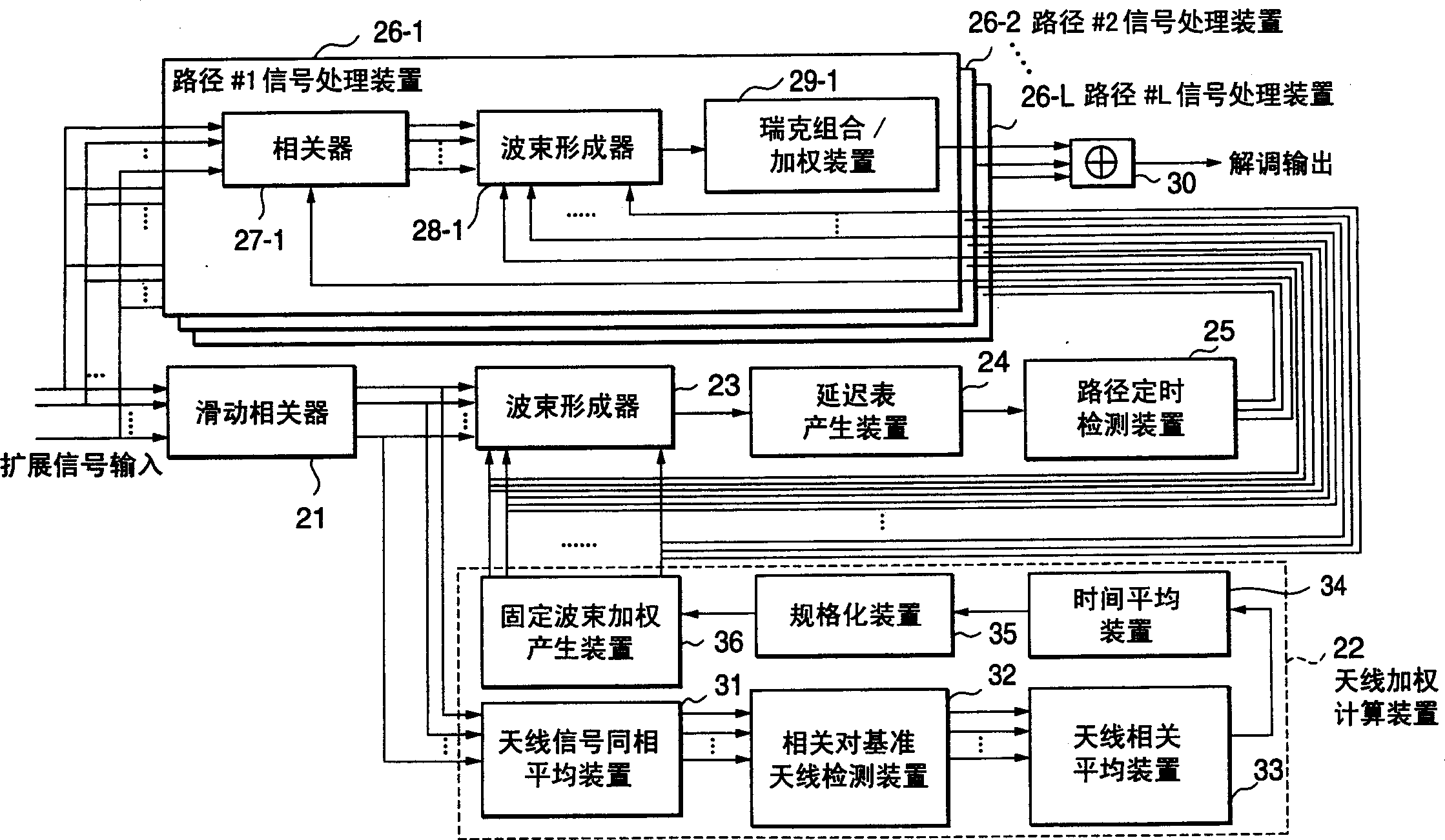
[0103] Refer below image 3 A second adaptive antenna receiving apparatus according to a second embodiment of the present invention will be described.

[0104] As described above, in the first adaptive antenna receiving device, in the demodulation / reception section, antenna weights are calculated by the antenna weight calculation means 2-1 to 2-L, and beamforming is performed on demodulated signals. The despread signal is received at the corresponding path timing independently calculated on the input side of the demodulation / reception section (path signal processing means). In this case, any method can be used to calculate the per-path timing.

[0105] In contrast, in the second adaptive antenna receiving apparatus, antenna weights are calculated simultaneously with path timing calculations, and path timing is detected using a beamforming signal. Also in the demodulation / reception section, beamforming is performed at detected path timing using antenna weighting. This will b...


PUM


Abstract

In the adaptive antenna receiving device, the correlation between adjacent antennas is detected for each path, and a fixed beam in the direction of arrival of the path of a desired electric wave is formed from a vector generated by the average detected correlation, and each path is received and combined, Or despread and detect the correlation between adjacent antennas for each signal sequence with multiple chip timings, form a fixed beam for the direction of arrival of each signal sequence according to the vector generated by the average detected correlation, and form a fixed beam according to the direction of arrival from each signal sequence The delay table generated by the output of the signal sequence detects the path timing, or despreads each signal sequence with multiple chip timings to detect multiple correlations between adjacent antennas, and forms the signal from the vector generated by averaging the detected correlations A fixed beam in the direction of arrival of the sequence, path timing is detected based on a delay table generated from an output of each signal sequence, and each path is received and combined using the path timing and the fixed beam at the path timing.

Description

technical field [0001] The present invention relates to a kind of adaptive antenna receiving device, relate to a kind of receiving CDMA (Code Division Multiple Access) signal more specifically, and form an antenna directional beam adaptively, to receive desired electric wave, and eliminate interference automatically Adapt to the antenna receiving device. Background technique [0002] Since CDMA can increase user capacity, CDMA is considered as a radio access scheme of the next generation mobile communication cellular system. However, at the receiving side of the base station, signals of simultaneously accessed users interfere with each other. In order to eliminate the interference between user signals, an adaptive array antenna has been proposed. [0003] Adaptive array antennas receive signals using multiple antennas, and use complex numbers to weight and combine the received signals. Next, the adaptive array antenna forms a directional beam by controlling the amplitude ...

Claims


Application Information

Patent Timeline
IPC IPC(8): H01Q3/26H04B1/707H04B1/7115H04B7/08
CPCH04B1/7113H04B1/712H04B7/0854H04B7/086H01Q3/26
Inventor 吉田尚正
Owner NEC CORP
Learn More