Automatic rotator of camera head

A technology of automatic rotation and camera, which is applied in the direction of optics, instruments, camera bodies, etc., can solve time-consuming and labor-intensive problems, and achieve the effects of high control accuracy, time-saving, labor-saving and high efficiency

Inactive Publication Date: 2002-12-25
安黎 +1
View PDF0 Cites 5 Cited by
  • Summary
  • Abstract
  • Description
  • Claims
  • Application Information

AI Technical Summary

Problems solved by technology

Time-consuming and labor-intensive

Method used


Image

  • Automatic rotator of camera head
  • Automatic rotator of camera head
  • Automatic rotator of camera head

Examples


Embodiment Construction

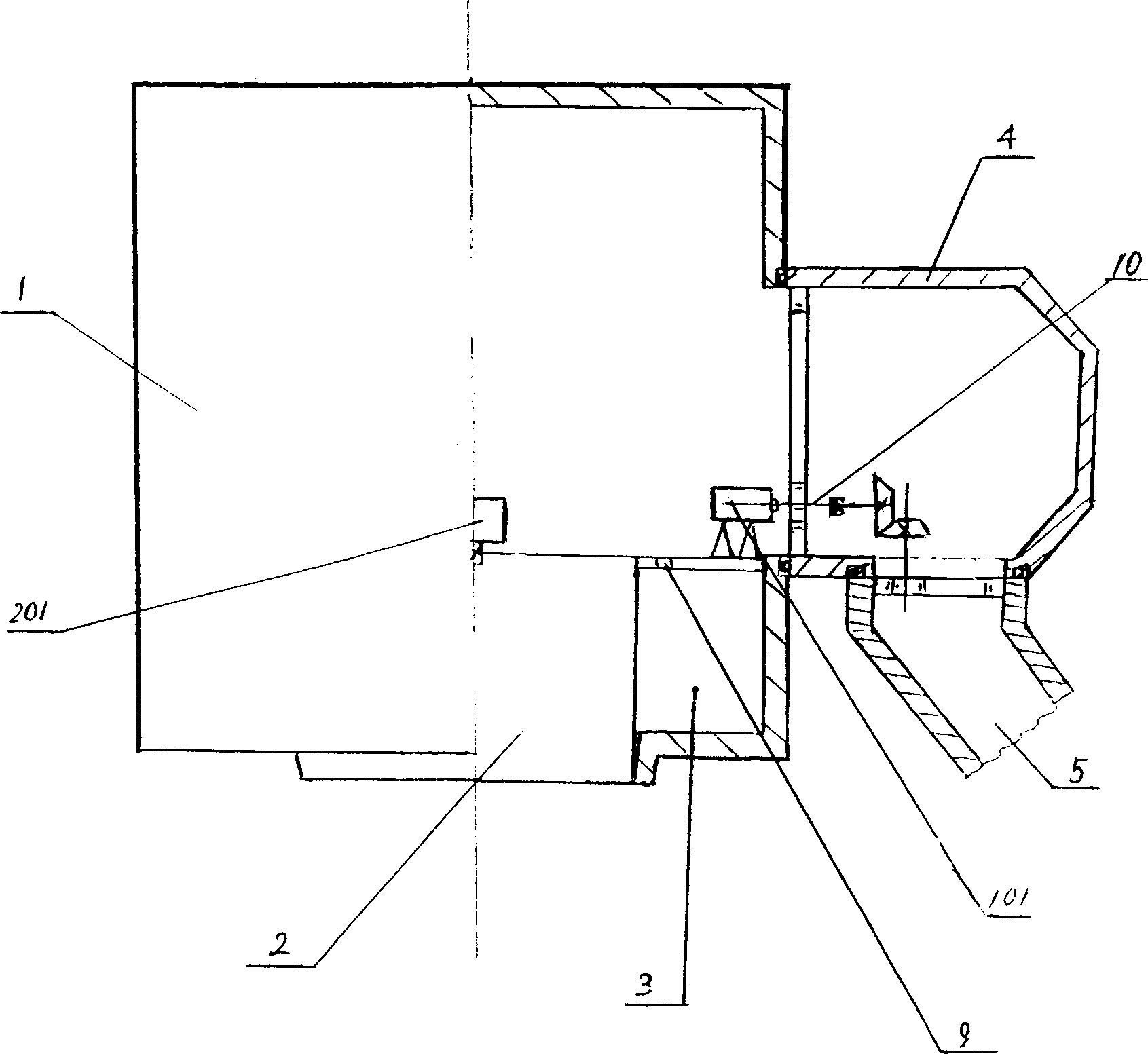
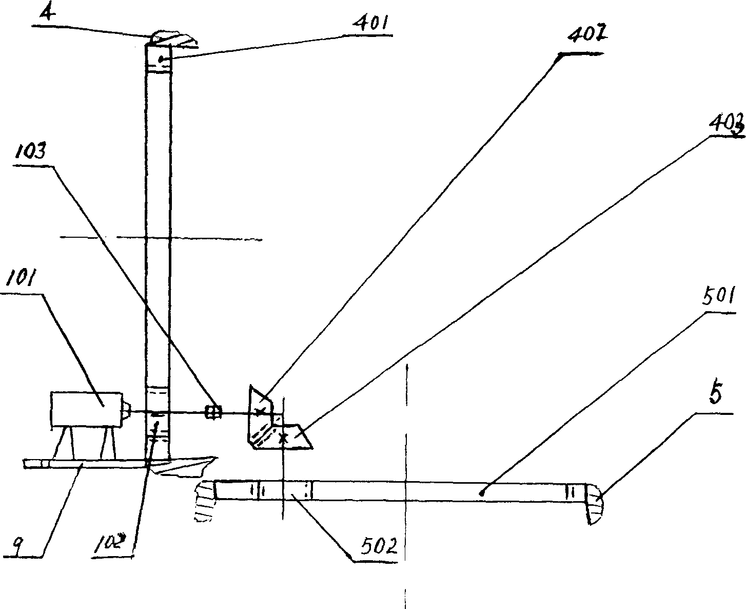
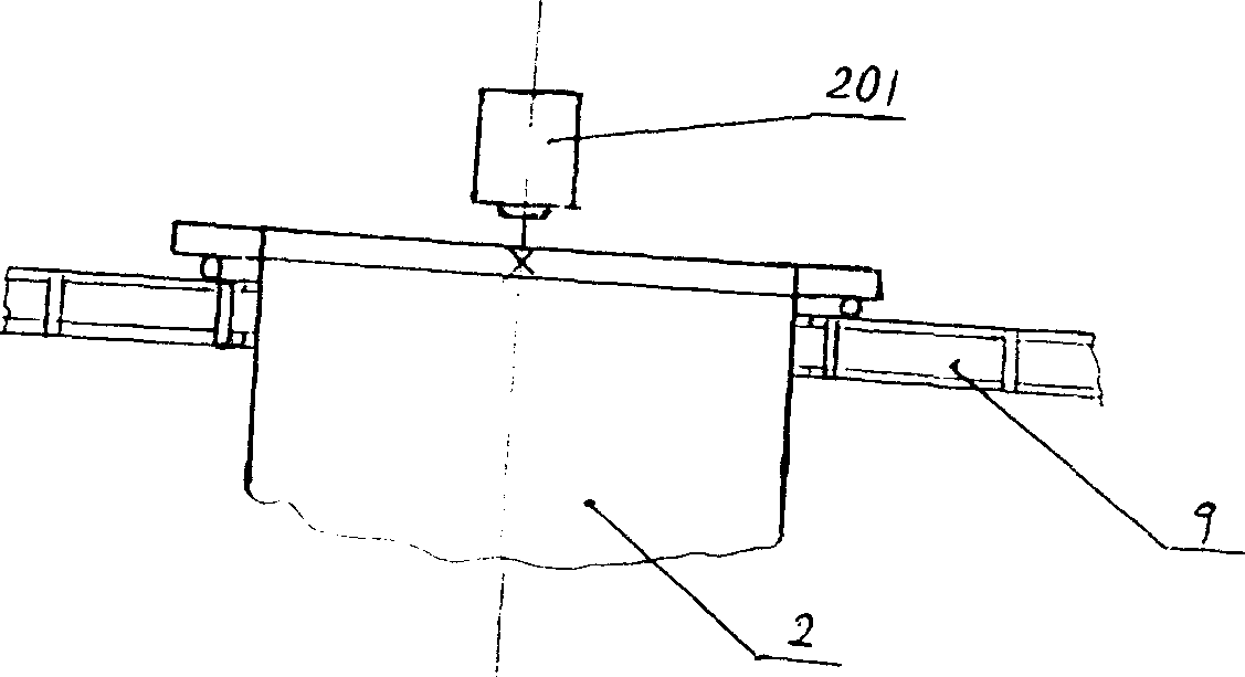
[0020] The structure of the invention is as figure 1 Shown: an automatic camera rotation device, including: a housing 1 and a camera 2 set therein, the housing 1 is movably matched with a movable arm 5 through a rotating head 4, a fixing frame 9 is threadedly connected with the housing 1, and the camera 2 is The fixed frame 9 is dynamically matched; the motor 101 is fixed on the fixed frame 9, and the motor 101 meshes with the gear ring 401 fixed to the rotating head 4 and the gear ring 501 fixed to the movable arm 5 through the transmission mechanism 10. The shaft of the decelerating motor 201 and the camera 2Fixed connection; the housing 1 is provided with an electrical component board 3 to connect the motor 101 and the geared motor 201.

[0021] The motor 101 is connected with the pinion 102 through the sliding key, the pinion 102 is meshed with the fixed ring gear 401 of the rotating head 4, the bevel gear 402 is axially connected with the pinion 102 through the electromagnet...


PUM


Abstract

An automatic rotor of camera head is disclosed. The casing containing the camera head is matched with movable arm via rotation head. The camera head is fit to fixer in movable mode. The motor fixed to said fixer is engaged via driven mechanism with the toothed rings of rotation head and movable arm. The axle of speed-reducing motor is fixed to camera head. The rotation of camera head can be controlled remotely, by itself, or electrically. Its advantage is high control precision.

Description

Technical field [0001] The invention relates to an automatic camera rotation device for a video display table. Background technique [0002] The camera of the video showcase cannot be rotated automatically and cannot be remotely controlled. The main participant needs to leave the video showcase often to give lectures in front of the display device. Some main speakers need to explain from different angles and frequently rotate the object when explaining the real object. When some presenters explain the manuscript, they often need to print a full page of manuscript paper (A4 format) on the display device before leaving the display stand. This can result in small fonts and unreadable due to the camera's own defects. At present, it is necessary to solve such problems. It is necessary to explain that people go back and forth between the display device and the video booth many times, and manually rotate the camera by hand and move the materials or objects needed to be demonstrated, whi...

Claims


Application Information

Patent Timeline
Patent Type & Authority Applications(China)
IPC IPC(8): G03B17/12
Inventor 安黎王欣
Owner 安黎
Why Eureka
Try Eureka