Position detecting devices

A technology for detecting devices and detecting switches, which is applied in the direction of measuring devices, utilizing fluid devices, measuring fluid pressure, etc., can solve the problems of poor versatility, restricting the installation space and installation position of position detection devices, and achieve simplified operation and improved installation freedom Effect

Inactive Publication Date: 2003-01-15
SMC CORP
View PDF1 Cites 6 Cited by
  • Summary
  • Abstract
  • Description
  • Claims
  • Application Information

AI Technical Summary

Problems solved by technology

Therefore, the installation space and installation location of the entire position detection device are limited.
Traditional position detection devices perform poorly in terms of versatility

Method used


Image

  • Position detecting devices
  • Position detecting devices
  • Position detecting devices

Examples


Embodiment Construction

[0021] best practice

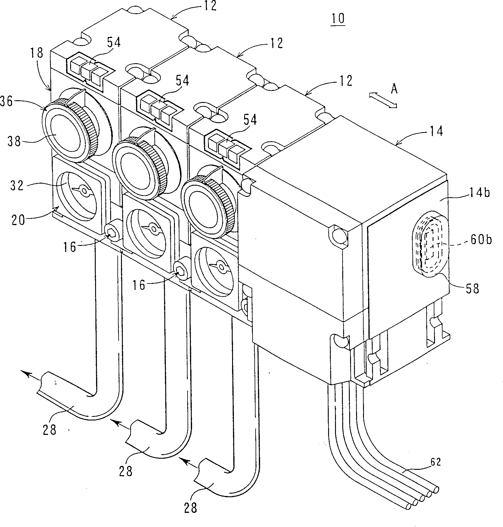
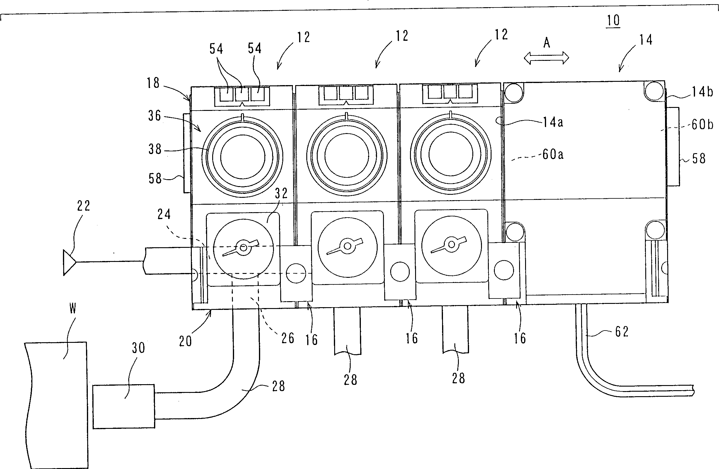
[0022] refer to figure 1 , reference numeral 10 denotes a position detection device according to an embodiment of the present invention.

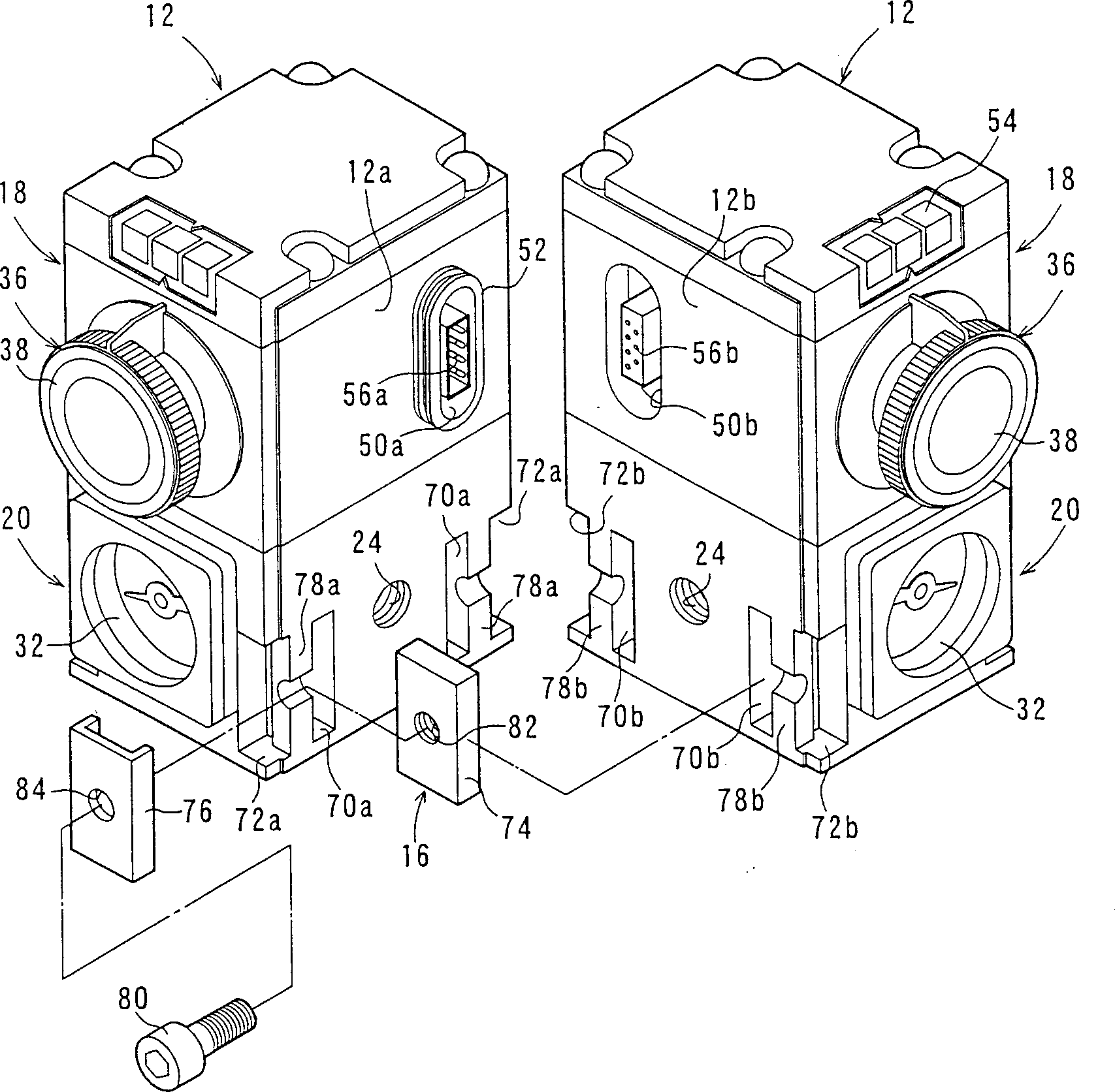
[0023] This position detection device 10 comprises: a plurality of (for example three) pressure detection switches 12 connected together along the direction shown by arrow A, a junction box 14 that can be connected with the other end of the pressure detection switch 12 along the stacking direction and the The pressure detection switch 12 is connected together to the fixing mechanism 16 .

[0024] Such as Figures 1 to 4 As shown, the pressure sensing switch 12 includes a housing portion 18 and a channel block portion 20 connected together. A feeding channel 24 communicated with an air source (fluid source) 22 is along the connecting direction (see Figures 2 to 5 The direction of arrow A in ) is formed through the channel block portion 20 .

[0025] Such as Figure 5 As shown, feed channel 24 bifurcates into a t...


PUM


Abstract

The present invention relates to a position-detecting device. Each of pressure-detecting switches (12) to be connected to one another has a first connector 56a) provided at one side section (12a) and a first connector (56b) provided at the other side section (12b). Electric wiring is mutually effected for the pressure-detecting switches (12) by attaching / detaching the first connectors (56a, 56b). The pressure-detecting switches are mutually fixed by using a fixing mechanism (16) arranged for the side sections to effect the function for mutually attaching / detaching the pressure-detecting switches (12).

Description

field of invention [0001] The present invention relates to a position detection device comprising a plurality of pressure detection switches having a detection nozzle for spraying fluid fed from a fluid source into a detection channel toward a target and controlling the fluid fed from the fluid source The flow rate of the fluid flowing to the comparison channel, so as to detect whether the pressure in the detection channel reaches the specified pressure in the comparison channel. Background technique [0002] The position detection device usually uses the back pressure of the nozzle to judge whether the workpiece is supported on the support surface. For example, Japanese Patent Laid-Open No. 2000-141166 discloses such a position detecting device. [0003] As shown in FIG. 6, each pressure detection switch of the position detection device includes a housing 1 and a channel block (unit) 2, and the housing 1 and the channel block 2 are integrally assembled together. Although ...

Claims


Application Information

Patent Timeline
Patent Type & Authority Applications(China)
IPC IPC(8): G01B13/00B23Q17/00G01L19/00
CPCG01L19/0015B23Q17/00
Inventor 奥山智幸齐藤充浩竹内良祐
Owner SMC CORP
Why Eureka
Try Eureka