Projector including a connection mechanism rotatably connecting a projector main body to an image output device

a technology of projector and image output device, which is applied in the field of projectors, can solve the problems of lowering the operation of the projector, and achieve the effect of improving the operation

Active Publication Date: 2014-08-05
SEIKO EPSON CORP
View PDF18 Cites 4 Cited by
  • Summary
  • Abstract
  • Description
  • Claims
  • Application Information

AI Technical Summary

Benefits of technology

[0008]An advantage of some aspects of the invention is to provide a projector for making it possible to freely change the position of the operation section in accordance with the installation conditions, and thus enhancing the freedom of installation.

Problems solved by technology

However, in the projector described in Patent Document 1, since the position of the DVD input section is fixed to the opposite side of the projection side of the projector, there has been caused a problem that the position of the operation section becomes far from the user in the case in which the projector is located, for example, on the rear side, the right, or the left of the user, thus the operationality of the projector is lowered.

Method used


Image

  • Projector including a connection mechanism rotatably connecting a projector main body to an image output device
  • Projector including a connection mechanism rotatably connecting a projector main body to an image output device
  • Projector including a connection mechanism rotatably connecting a projector main body to an image output device

Examples


modified example of embodiments

[0111]It should be noted that the invention is not limited to the embodiment described above, but includes modifications and improvements in a range where the advantages of the invention can be achieved.

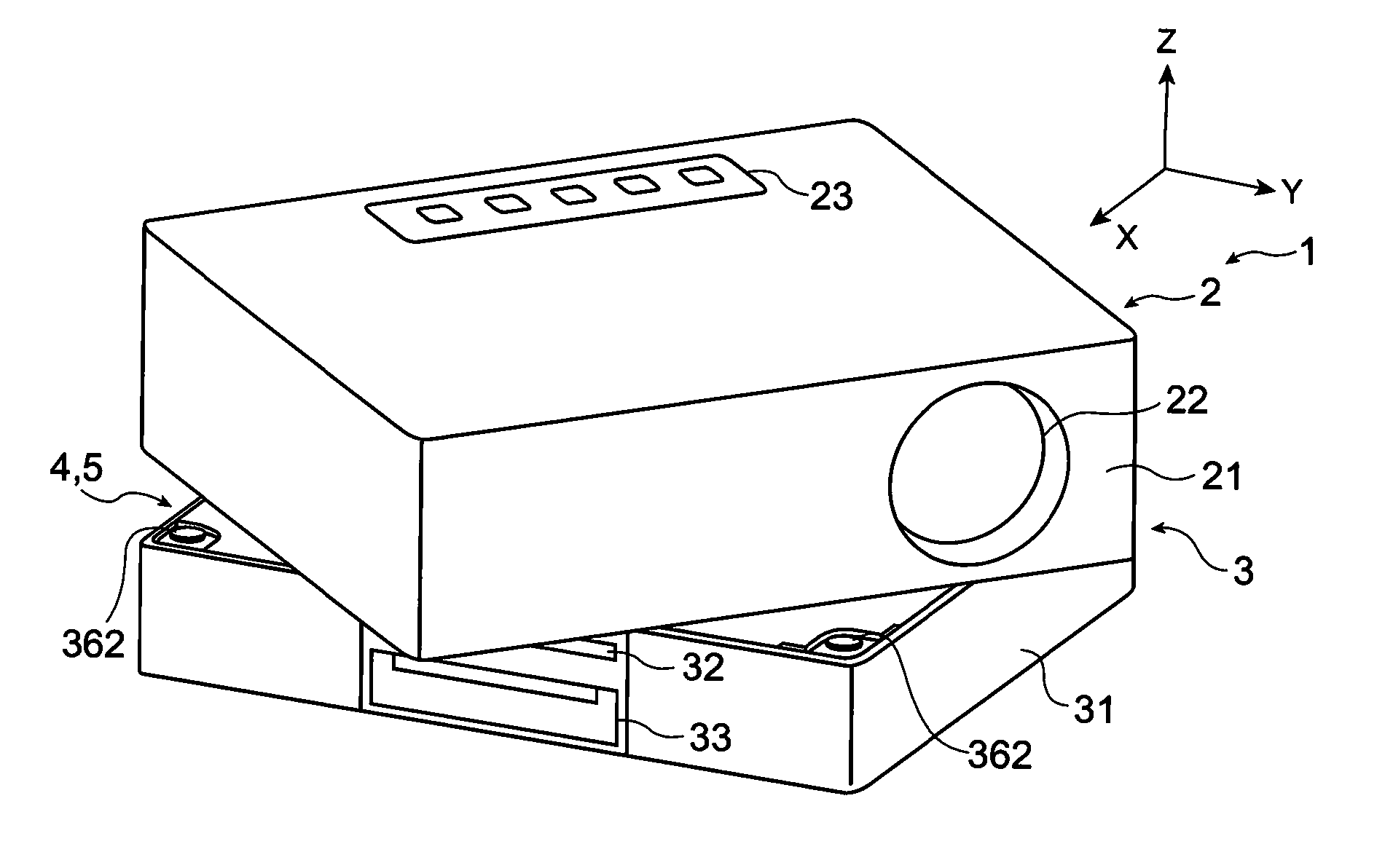
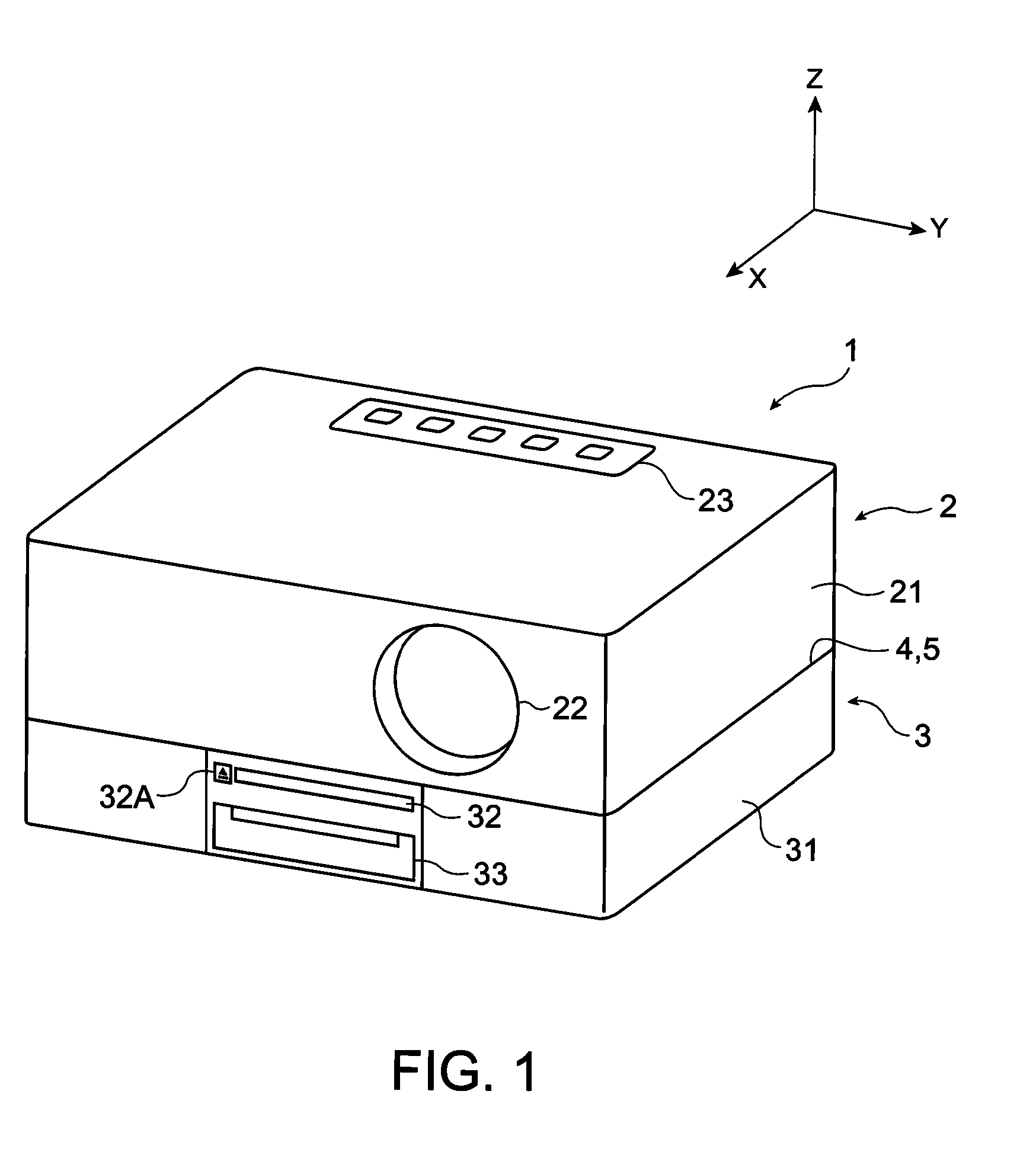
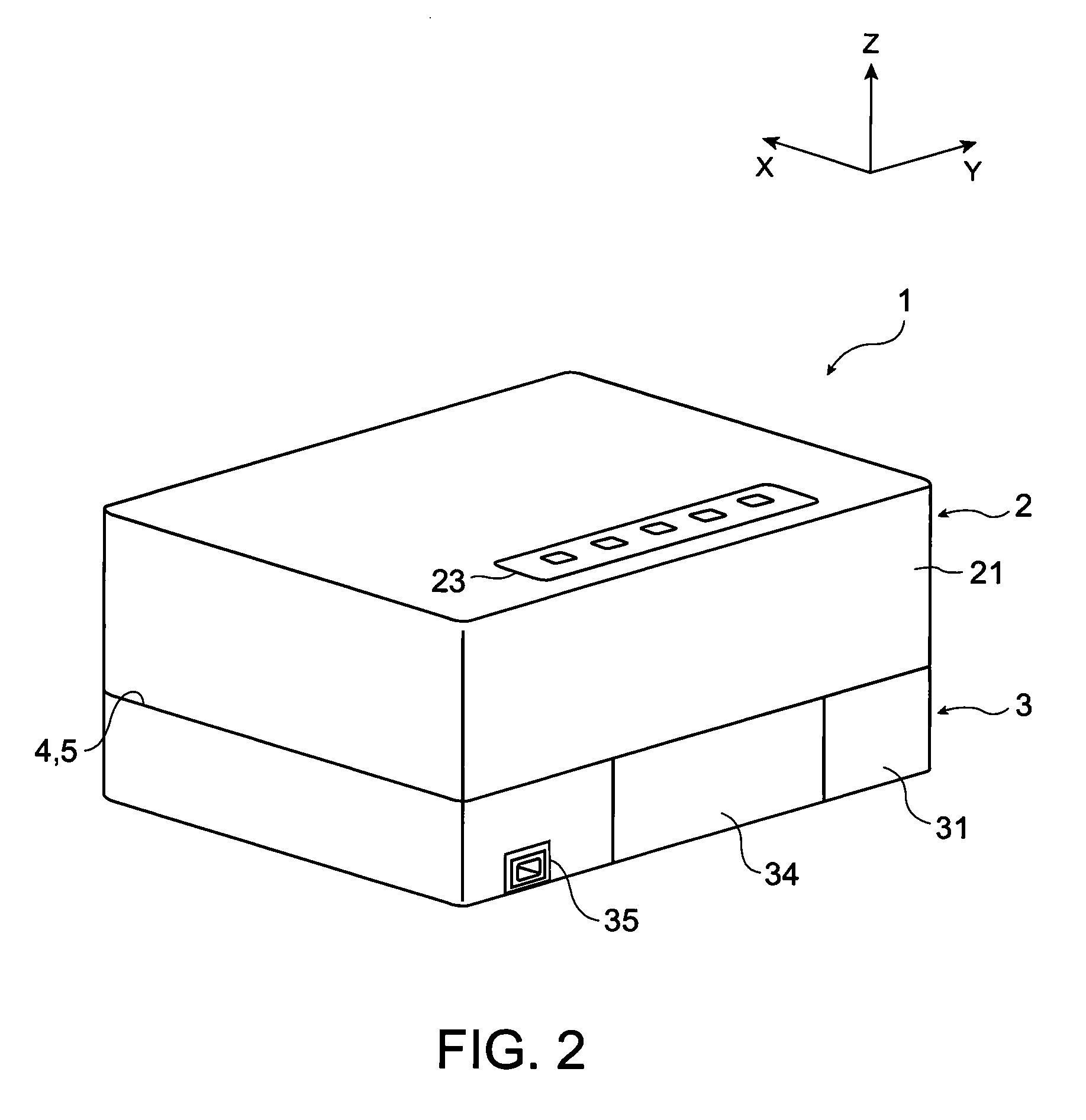
[0112]Although in the embodiment the projector main body 2 is mounted on the upper side of the DVD player 3, the image output device can be mounted on the upper side of the projector the other way around.

[0113]Although in the embodiment the projector main body 2 and the DVD player 3 are disposed in a stacked manner in the vertical direction, it is also possible to dispose them adjacent to each other in a horizontal direction. In short, it is enough for the projector main body and the image output device to be disposed so as to be opposed to each other.

[0114]Although in the embodiment the DVD player 3 is exemplified as the image output device, a video player or the like, for example, can also be adopted as the image output device, and after all, any devices for outputting the image in...


PUM


Abstract

A projector includes a projector main body for enlargedly projecting the optical image, an image output device for outputting the image information to the projector main body, and a connection mechanism interposing between the projector main body and the image output device, and for connecting the projector main body and the image output device to each other, wherein the projector main body and the image output device are disposed so as to be opposed to each other, the connection mechanism includes a plate-like member fixed to either one of the projector main body and the image output device, and a rotatable member fixed to the plate-like member and attached to the other of the projector main body and the image output device, and for making the plate-like member rotatable relatively to the other of the projector main body and the image output device.

Description

BACKGROUND[0001]1. Technical Field[0002]The present invention relates to a projector.[0003]2. Related Art[0004]In the past, there has been known a projector provided with a projector main body for modulating a light beam emitted from a light source in accordance with input image information to form an optical image and then enlargedly projecting the optical image thus formed, and an image output device for outputting the image information to the projector main body (see e.g., JP-A-2006-72037 (Patent Document 1)).[0005]In the projector described in Patent Document 1, the projector main body is mounted on the image output device (e.g., a Digital Versatile Desk (DVD) player) via a partitioning member. Further, on the rear face of the DVD player there are disposed a DVD input section for inputting a DVD and a speaker for outputting the sound.[0006]Incidentally, such a projector integrally composed of the image output device and the projector main body is mainly used inside a room in a h...

Claims


Application Information

Patent Timeline
Patent Type & Authority Patents(United States)
IPC IPC(8): G03B21/14G03B21/22H04N9/31
CPCG03B21/14G03B21/145G03B21/22H04N9/3141
Inventor KIMURA, TETSUSHI
Owner SEIKO EPSON CORP
Why Eureka
Try Eureka