Antenna Apparatus

a technology of antenna apparatus and antenna, applied in the direction of digital transmission, transmission, duplex signal operation, etc., can solve the problems of difficult to secure optimal sensitivity, the antenna apparatus for use cannot be tilted in the direction of a satellite after, etc., and achieve the effect of increasing the freedom of installation

Inactive Publication Date: 2006-11-02
MITSUMI ELECTRIC CO LTD
View PDF18 Cites 4 Cited by
  • Summary
  • Abstract
  • Description
  • Claims
  • Application Information

AI Technical Summary

Benefits of technology

[0006] It is therefore an object of the present invention to provide an antenna apparatus whose angle is freely adjustable even after the antenna apparatus is installed in the interior of a motor vehicle, for example, in order to make optimum sensitivity available.
[0021] Also, as the hook holes are provided additionally, the cable can be drawn out of an upper or a lower side, whereby installation freedom is increased.

Problems solved by technology

However, regarding the directional sensitivity of the antenna apparatus, it is difficult to secure optimum sensitivity when the antenna apparatus is actually installed because the antenna apparatus is mounted inside the vehicle but not set in such an environment that a shielding member is existent.
Moreover, since the mounting of the antenna apparatus is carried out by attaching the base of the antenna case securely onto any planar face in the interior of the vehicle as described above, the antenna apparatus for use cannot be tilted in the direction toward a satellite after the antenna apparatus is installed in the interior of the vehicle.

Method used


Image

  • Antenna Apparatus
  • Antenna Apparatus
  • Antenna Apparatus

Examples


Embodiment Construction

[0042] An antenna apparatus according to the invention will now be described in detail by reference to the accompanying drawings.

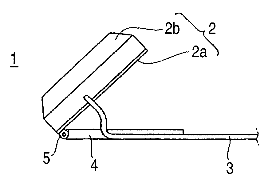
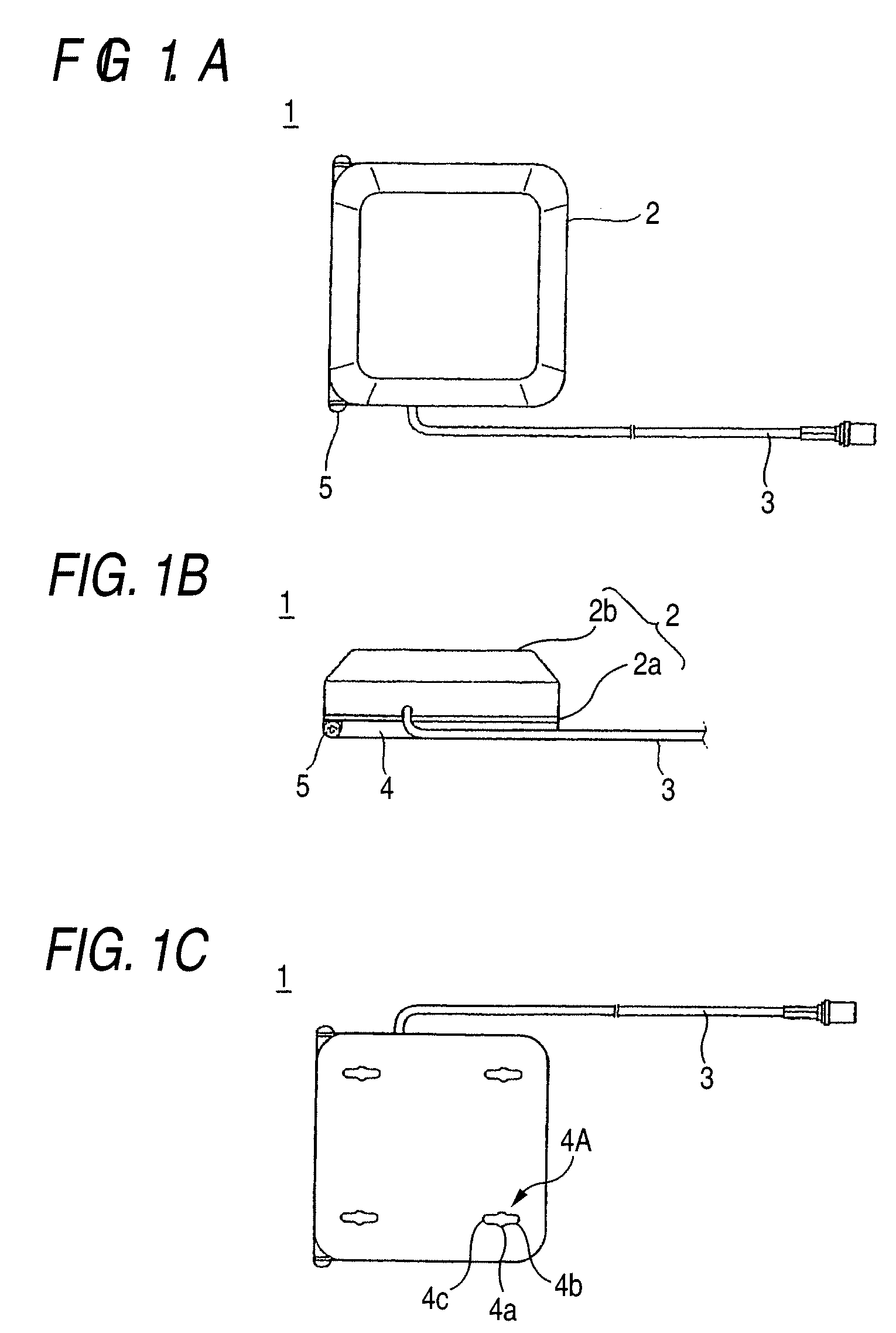
[0043]FIGS. 1A to 1C is an external view of an antenna apparatus 1 according to the invention. FIG. 1A is a top view of the antenna apparatus 1 as seen from the vertex direction, FIG. 1B is a side view of the antenna apparatus 1 as seen from its side, and FIG. 1C is a bottom view of the antenna apparatus 1 as seen from its base side. The antenna apparatus 1 shown in this illustrative example is mounted on any planar face inside a motor vehicle, preferably mounted on a planar face near the window of the motor vehicle and used to receive radio waves for transmitting GPS signals, satellite radio broadcasting signals, cellular telephone signals and the like.

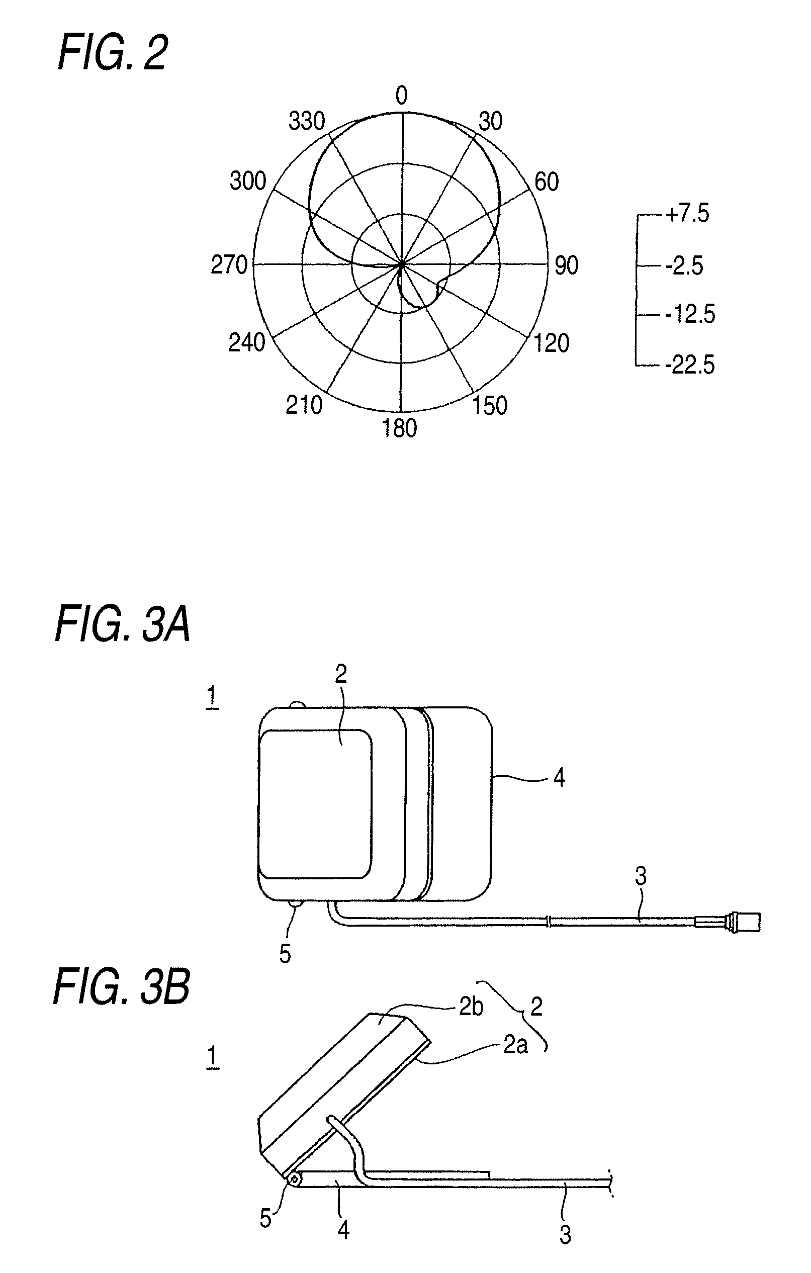
[0044] The antenna apparatus 1 has an antenna element having directivity in the vertex direction. FIG. 2 shows an example of the directivity of the antenna element. The antenna apparatus 1 has an antenna ...


PUM


Abstract

An antenna apparatus includes an antenna element having directivity in a vertex direction, an antenna case containing the antenna element, an antenna base coupled to the antenna case, and attached onto an installation face, and an angle regulator adjusting a relative angle between the antenna case and the antenna base.

Description

CROSS-REFERENCE TO RELATED APPLICATIONS [0001] This application is a continuation application of U.S. Ser. No. 10 / 700,620 filed Nov. 5, 2003, and the complete contents are incorporated herein by reference.BACKGROUND OF THE INVENTION [0002] The present invention relates to an antenna apparatus and more particularly to an antenna apparatus which is mounted, for example, in the interior of a motor vehicle and enables good sensitivity to be secured. [0003] A typical on-board antenna apparatus is mounted in any position inside a vehicle, preferably mounted near the window of the vehicle. The antenna apparatus is installed with a helical antenna element in the form of a helical conductor, for example. The helical antenna element is an omnidirectional antenna element as shown by a radiation pattern in FIG. 11, for example. The mounting of the antenna element is carried out by attaching the base of an antenna case securely onto a portion inside a motor vehicle normally with a double-sided t...

Claims


Application Information

Patent Timeline
Patent Type & Authority Applications(United States)
IPC IPC(8): H01Q1/24H01Q1/12H01Q1/22H01Q3/04
CPCH01Q1/12H01Q3/04H01Q1/22
Inventor NORO, JUNICHISASAKI, KUMEO
Owner MITSUMI ELECTRIC CO LTD
Why Eureka
Try Eureka