Button switch

A switch and button technology, applied in the structural field of small button switches, can solve the problems of reduced terminal welding range and difficulty in improving welding strength, etc.

Inactive Publication Date: 2003-03-19
ALPS ALPINE CO LTD
View PDF0 Cites 4 Cited by
  • Summary
  • Abstract
  • Description
  • Claims
  • Application Information

AI Technical Summary

Problems solved by technology

[0010] Therefore, the problem that arises is: along with the miniaturization requirement to the whole switch in recent years, the width of the welding terminal is also reducing, so the welding range of the terminal is reduced, and the welding strength of the terminal on the above-mentioned conductive pattern 17a is very low. Difficult to improve

Method used


Image

  • Button switch
  • Button switch
  • Button switch

Examples


Embodiment Construction

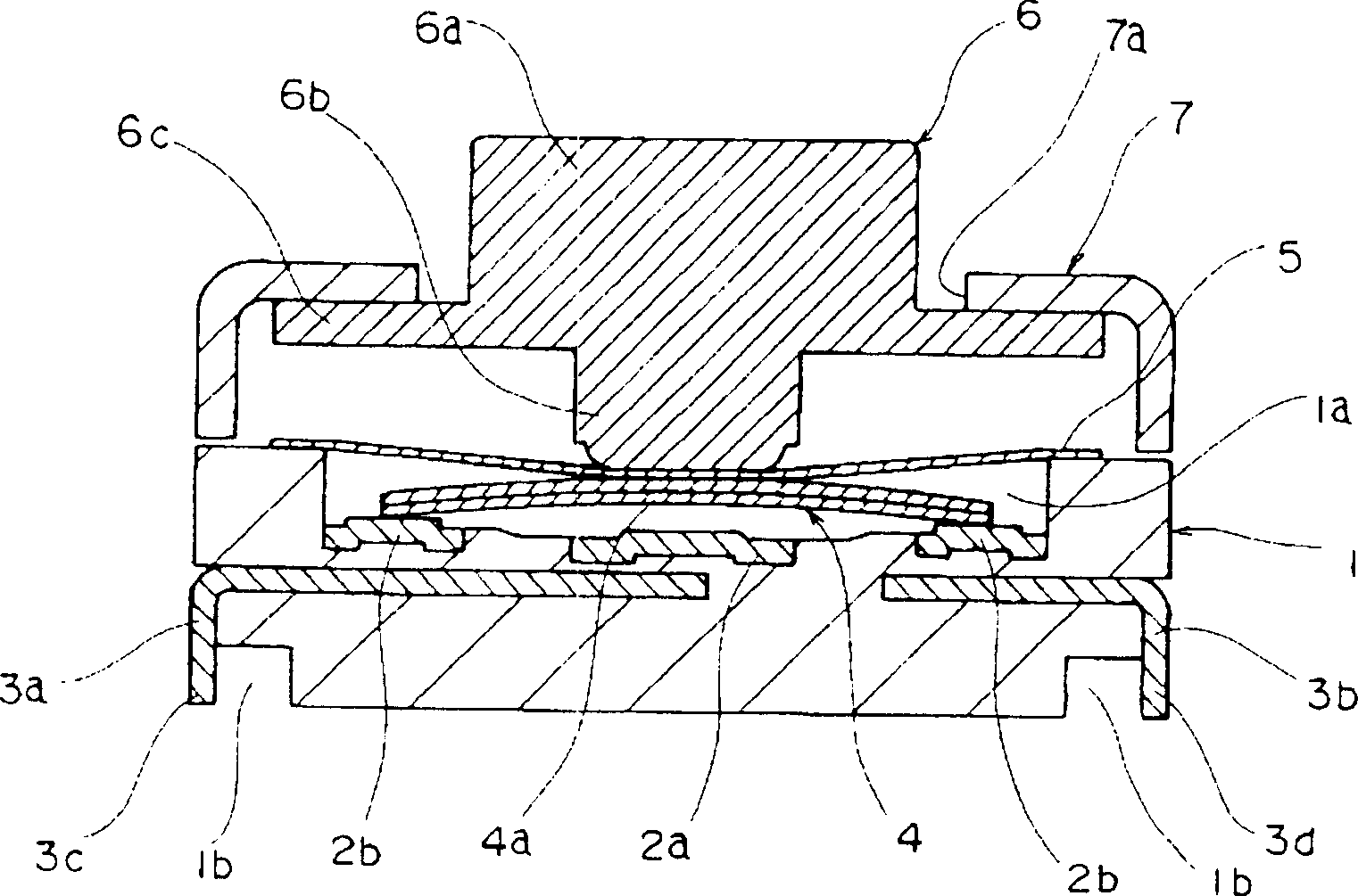
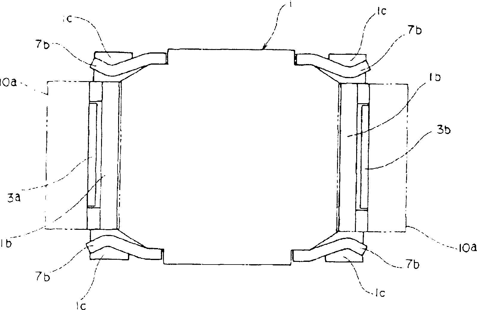
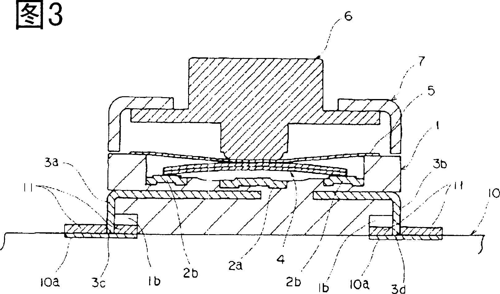
[0030] An embodiment of the push button switch of the present invention is shown in figure 1 ~ Figure 7. Figure 1~Figure 4 Showing one embodiment of the push button switch of the present invention, figure 1 It is a vertical sectional view of the push button switch, figure 2 It is the bottom view of the push button switch. Fig. 3 is a longitudinal sectional view showing the mounting state (before reflow soldering) of the push button switch on the circuit board, Figure 4 It is a longitudinal sectional view of the main part showing the mounting state of the push button switch on the circuit board (after reflow soldering).

[0031] exist figure 1 , figure 2 Among them, the casing 1 is a box-shaped body formed of an insulating material such as synthetic resin, and has an accommodating portion 1a inside, an opening on the top, and a square box shape. At the center of the inner bottom surface of the housing portion 1a of the case 1, a central fixed contact 2a made of conduc...


PUM


Abstract

To respond to miniaturization needs of a switch as a whole and provide a push-button switch structure which can aim at improvement of soldering strength of a fixed terminal to a conductive pattern. The switch is provided with a housing 1 equipped with a plurality of fixed contacts 2a, 2b, a movable contact 4 housed in the housing 1 in free contact with and separation from the fixed contacts 2a, 2b and fixed terminals 3a, 3b electrically conducted with the fixed contacts 2a, 2b and protruding toward outside of the housing 1. The fixed terminals 3a, 3b are formed in a linear shape parallel along sidewalls of the housing 1, and the sidewalls of the housing 1 opposing the linear fixed terminals 3a, 3b are provided with a notched part 1b each to be estranged from side face parts of the fixed terminals 3a, 3b.

Description

technical field [0001] The present invention relates to a push button switch that makes a movable contact and a fixed contact contact or disconnect by pressing, and particularly relates to the structure of a small push button switch used in portable electronic equipment and the like. Background technique [0002] The structure of the conventional push button switch is shown in Fig. 8 and Fig. 9 . Fig. 8 is a longitudinal sectional view of the push button switch, and Fig. 9 is a longitudinal sectional view showing the mounted state of the push button switch. [0003] Pushbutton switches in the past consisted of the following parts: [0004] Square housing 21, wherein there is a receiving part; central fixed contact 22a and surrounding fixed contact 22b, both of which are arranged in the receiving part of the housing 21; movable contact 24, which is arranged at the central fixed contact 22a and surrounding fixed contact 22b The opposite side; the cover plate 25, which is arr...

Claims


Application Information

Patent Timeline
Patent Type & Authority Applications(China)
IPC IPC(8): H01H13/04H01H9/02H01H13/52
Inventor 小泽健
Owner ALPS ALPINE CO LTD
Why Eureka
Try Eureka