
Digital electric power meter

An electric energy metering device, digital technology, applied in the direction of measuring device, measuring electric variable, electric power measurement by current/voltage, etc.

Inactive Publication Date: 2003-04-09
刘英彰
View PDF0 Cites 1 Cited by
  • Summary
  • Abstract
  • Description
  • Claims
  • Application Information

AI Technical Summary

Problems solved by technology

[0003] 1. Traditional electricity meters are often placed in the user's premises, making it difficult to read their electricity consumption data
[0004] 2. The traditional watt-hour meter relies on the magnetic force formed by the loop current to calculate the electricity consumption by the rotation of the disk in the electromagnetic induction watt-hour meter. However, this kind of watt-hour meter will cause the watt-hour meter to fail due to the change of the magnetic force and the wear of the mechanical bearing. precise
[0005] 3. Traditional watt-hour meters will affect the speed of the tachometer due to external magnetic field interference, resulting in inaccurate watt-hour meters
[0006] 4. Traditional watt-hour meters cannot be connected to the interface, so the meter cannot be read automatically by the instrument, and only manual meter reading can be used, which will damage the rights and interests of electricity users due to misreading or misreading
[0007] 5. Traditional watt-hour meters are vulnerable to electricity theft
This invention is aimed at the detection and protection of electricity theft by users, and also does not provide functions such as power consumption data memory during power outages, remote automatic meter reading, and remote power consumption rate setting.

Method used


Image

  • Digital electric power meter
  • Digital electric power meter
  • Digital electric power meter

Examples


Embodiment Construction

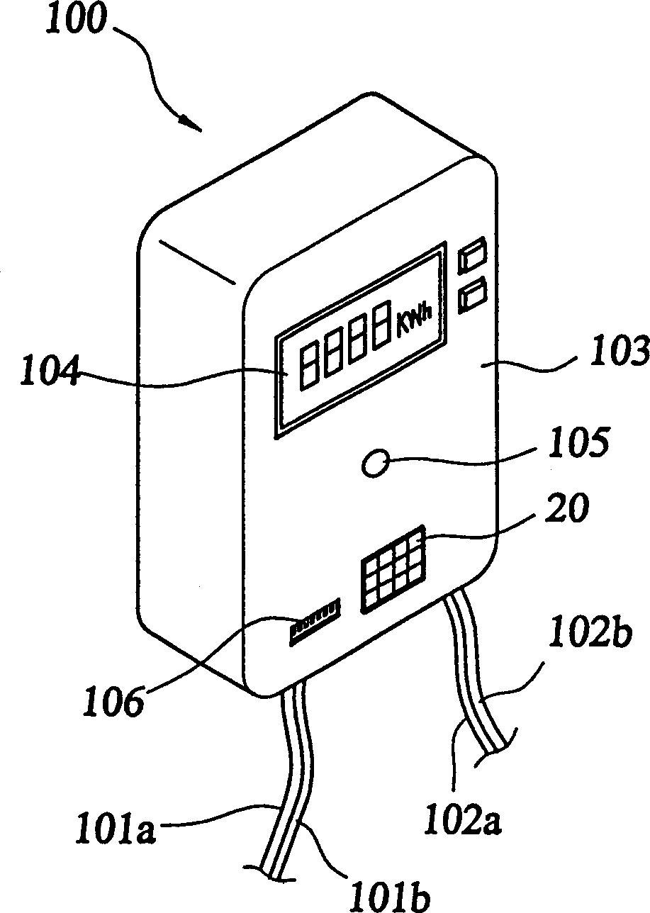
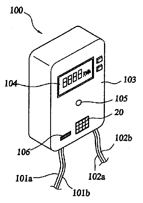
[0047] see figure 1 As shown, it is a perspective view of an embodiment of the digital electric energy metering device of the present invention. The digital electric energy metering device 100 is installed before the power supply company transmits the AC power to the electric consumer to measure the electricity consumption of the electric consumer. The present invention connects to the AC power supply through a power input line 101a, 101b, and then connects the AC power supply to the electricity user through a power output line 102a, 102b.

[0048] On the front panel of the housing 103 of the electric energy metering device of the present invention, there is mainly a display unit 104, which can be an LED display unit or an LCD display unit, for displaying the electricity consumption value.

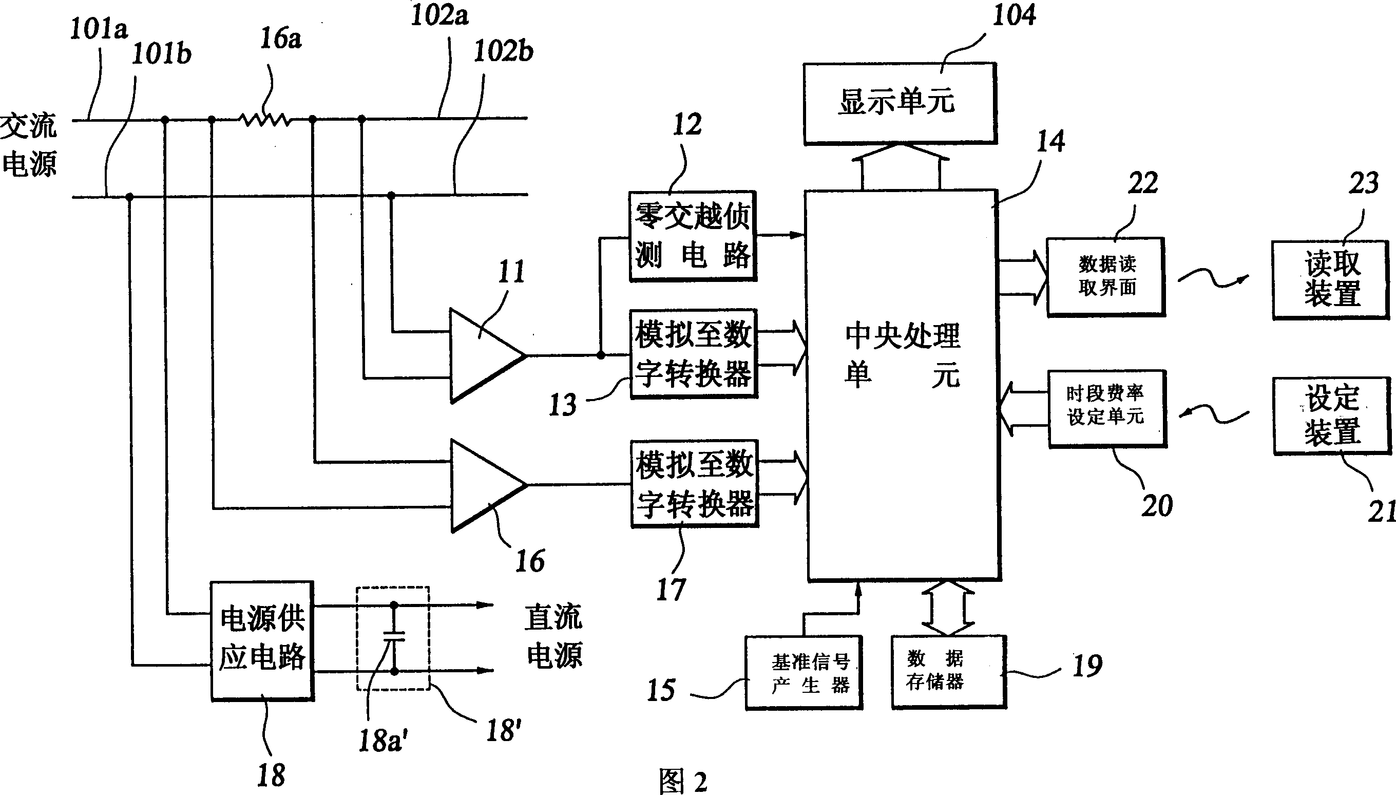
[0049] Please refer to FIG. 2, which is a control circuit diagram of the digital electric energy metering device of the present invention; the control circuit of the present invention is a...


PUM


Abstract

An electric energy metering device in digital type used to detect the electricity consuming state of a user and to display it for collecting the charge of the consumed electricity based on it by the electric power supply company includes a shell, a control circuit in the shell for accumulating the consumed electricity number of KWH for the user, a power source input line connected to AC power source for leading AC power to the control circuit, a power output line connected to the control circuit for leading AC power to the load of the user and a display unit on the shell for indicating the consumed electric data obtained by the control circuit.

Description

technical field [0001] The invention relates to an electric energy metering device, in particular to a digital electric energy metering device. Background technique [0002] The power supply company uses a watt-hour meter to record the electricity consumption and electricity consumption status of the power users, and then the meter reader will fill in the electricity consumption of each user every month, and the power supply company will calculate the power consumption according to the electricity consumption the amount of its electricity bill. This is the general mode of calculating electricity bills for electricity users, but this mode has many disadvantages, such as: [0003] 1. Traditional watt-hour meters are often placed inside the user, making it difficult to read their electricity consumption data. [0004] 2. The traditional watt-hour meter relies on the magnetic force formed by the loop current to calculate the electricity consumption by the rotation of the disk ...

Claims


Application Information

Patent Timeline
Patent Type & Authority Applications(China)
IPC IPC(8): G01R21/06G01R22/00
Inventor 刘英彰
Owner 刘英彰
Learn More