
Power supply device

a power supply device and power supply technology, applied in the direction of electric variable regulation, process and machine control, instruments, etc., can solve the problems of reducing the efficiency of distributing power in the power distribution system, and achieve the effect of improving the efficiency of distributing power

Active Publication Date: 2017-08-08
KONINK PHILIPS ELECTRONICS NV
View PDF12 Cites 0 Cited by
  • Summary
  • Abstract
  • Description
  • Claims
  • Application Information

AI Technical Summary

Benefits of technology

[0004]It is an object of the present invention to provide a power supply device for supplying power to an electrical consumer having a variable power consumption in a power distribution system, which allows for an improved efficiency of distributing the power within the power distribution system. It is a further object of the present invention to provide a power distribution system comprising the power supply device and the electrical consumer and a corresponding power distribution method and power distribution computer program.
[0006]Since the output current is not constant, but controlled depending on the power consumed by the electrical consumer, the output current can be adapted to the actually consumed power, thereby allowing for an improved efficiency of distributing the power in the power distribution system. In particular, if less power is consumed by the electrical consumer, a lower output current can be provided, thereby reducing losses in cables and electrical connectors of the power distribution system.
[0009]It is preferred that the power supply device comprises a power consumption detection unit for detecting the power consumed by the electrical consumer and a power supply for providing the output current depending on the detected power consumed by the electrical consumer. In particular, the power consumption detection unit is adapted to detect the output voltage of the power supply for detecting the power consumption, wherein the power supply is adapted to control the output current depending on the detected output voltage. This allows the power supply device to detect the power consumption of the electrical consumer in a relatively simple way just by detecting the output voltage of the power supply. The power supply may comprise a power converter for converting alternating current (AC) power to DC power to be supplied to the electrical consumer.
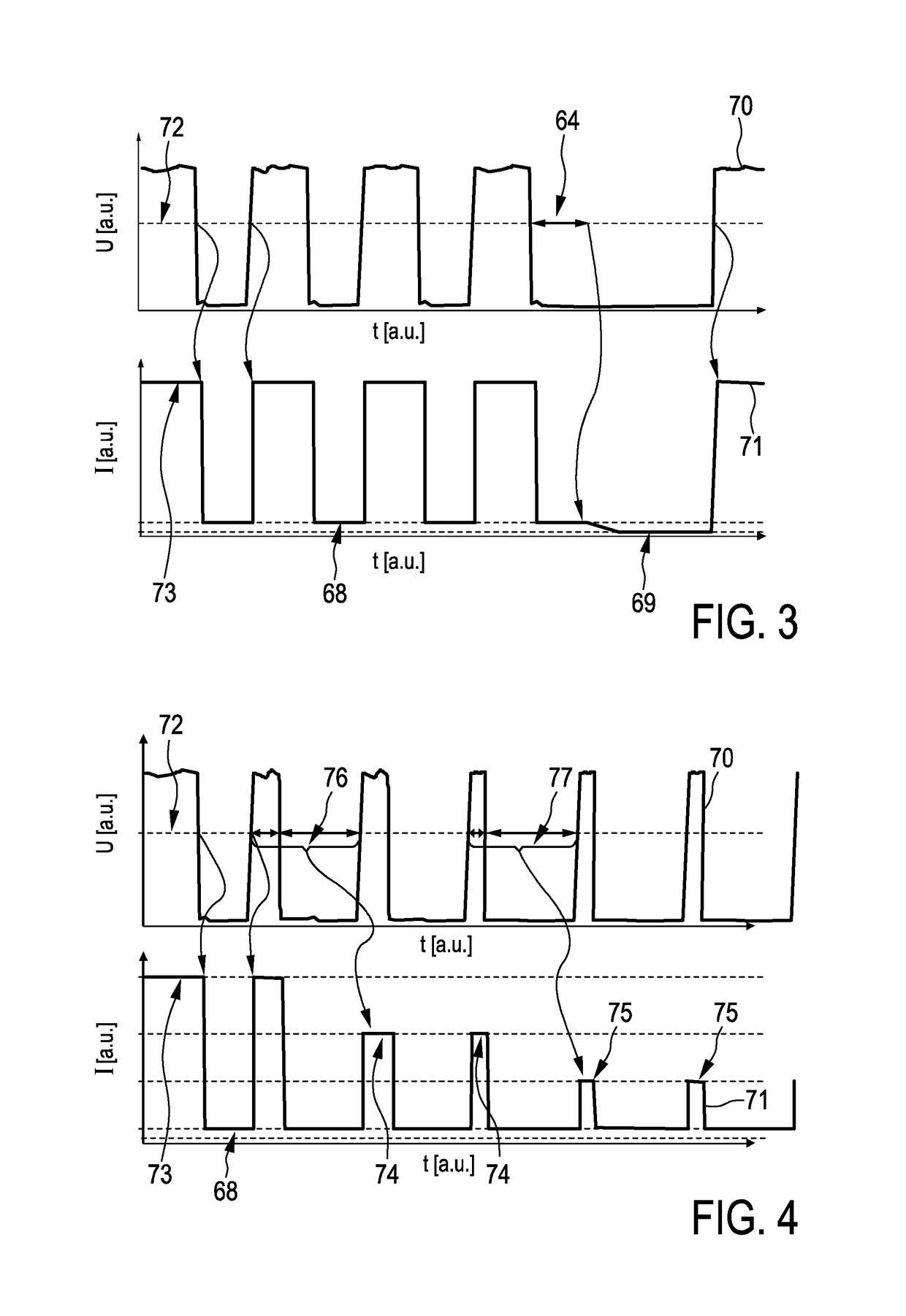
[0012]The power supply is preferentially adapted to provide a higher amplitude of the output current, when the amplitude of the detected output voltage is larger than a threshold voltage, and a lower amplitude of the output current, when the amplitude of the detected output voltage is smaller than the threshold voltage. The amplitude of the output current can therefore be modulated depending on the power consumed by the electrical consumer. In particular, if the electrical consumer is pulse-width modulated, the comparison of the amplitude of the detected voltage with the threshold voltage can yield the duty cycle of the PWM such that the power supply can be modulated in accordance with the duty cycle. The output power and, thus, losses in cables and possible other connecting elements are can therefore be reduced in accordance with a reduction of the power consumption of the electrical consumer due to the PWM. If the electrical consumer is a lamp with a dimming function provided by a pulse-width modulated shunt switch, the combination of the detected PWM duty cycles and the lower amplitude of the output current during short circuit periods, i.e. in shunted periods, can reduce losses during low power periods, in particular, off periods, of the PWM and improve flicker behavior over a full dim range.
[0015]In an embodiment at least one of the higher amplitude and the lower amplitude of the output current depends on the temporal length of the period in which the amplitude of the detected output voltage is smaller than the threshold voltage. For instance, the power supply can be adapted to provide the higher amplitude of the output current, when the amplitude of the detected output voltage is larger than the threshold voltage, provide a first lower amplitude of the output current, when the amplitude of the detected output voltage is smaller than the threshold voltage for a time being smaller than a temporal threshold, and provide a second lower amplitude of the output current being smaller than the first lower amplitude, when the amplitude of the detected output voltage is smaller than the threshold voltage for a time being larger than the temporal threshold. This functionality can allow the power supply device to also consider situations, in which the electrical consumer is completely switched off, thereby further reducing possible losses in cables and optional further connection elements.
[0017]Preferentially, at least one full period of the PWM, in particular, only one full PWM period, is used for determining the actual duty cycle from the detected voltage, wherein in the following period the amplitude of the output current can be set in accordance with the determined duty cycle. If the electrical consumer is a lamp like a light-emitting diode (LED) with a pulse-width modulated shunted dimming function, this can lead to a load side dimmed solution with a mixed analog current modulation. Lamps with such a driving scheme may provide high efficiency solid-state lighting (SSL) solutions for low dim levels. These lamps may be used in corridors or other spaces that need a minimal constant flux level, for instance, for emergency purposes and only full flux level, when in use.

Problems solved by technology

These voltage drops reduce the efficiency of distributing power in the power distribution system.

Method used


Image

  • Power supply device
  • Power supply device
  • Power supply device

Examples


Embodiment Construction

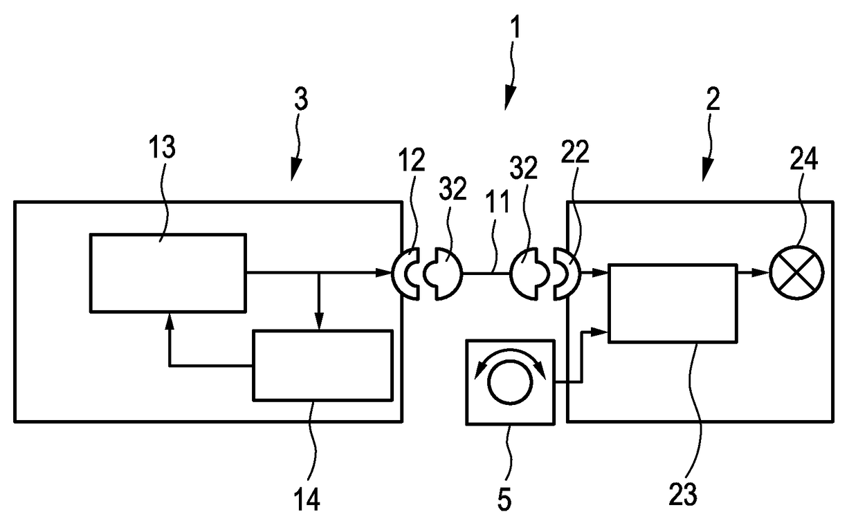
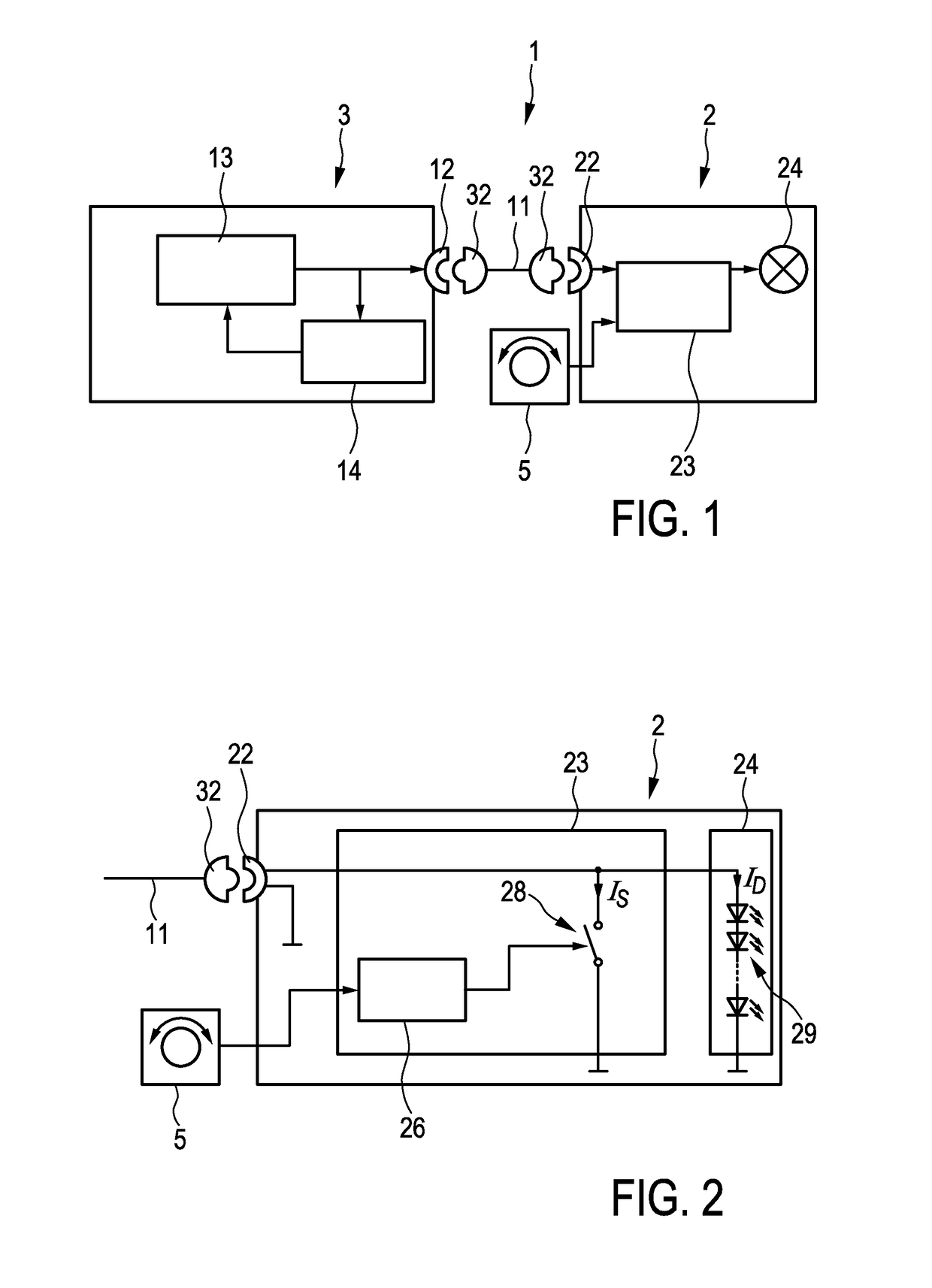
[0031]FIG. 1 shows schematically and exemplarily an embodiment of a power distribution system for distributing power from a power supply device 3 to an electrical consumer 2. In this power distribution system 1 the power supply device 3 and the electrical consumer 2 are electrically connected via a Cat 5 cable 11, which is coupled to the power supply device 3 and the electrical consumer 2 by using electrical connectors 12, 32, 22. The power distribution system 1 is adapted to distribute DC power, wherein the power supply device is output current controlled.

[0032]The power consumed by the electrical consumer 2 is variable by using a pulse-width modulated shunt circuit 23, wherein the PWM, i.e. the duty cycle of the PWM, is controllable by a user via a user control unit 5. In this embodiment, the electrical consumer 2 is a lamp comprising the user control unit 5, the pulse-width modulated shunt circuit 23 and a light source 24, wherein the user control unit 5 and the pulse-width modul...


PUM


Abstract

The invention relates to a power supply device (3) for supplying power to an electrical consumer (2) having a variable power consumption in a power distribution system (1), particularly in a DC power distribution system for lighting applications, wherein the power supply device (3) is output current controlled and is adapted to provide the output current depending on the power consumed by the electrical consumer (2). Since the output current is not constant, but controlled depending on the power consumed by the electrical consumer (2) being preferentially a lamp, the output current can be adapted to the actually consumed power, thereby allowing for an improved efficiency of distributing the power in the power distribution system (1). In particular, if less power is consumed by the electrical consumer (2), a lower output current can be provided, thereby reducing losses in cables and electrical connectors of the power distribution system.

Description

FIELD OF THE INVENTION[0001]The invention relates to a power supply device for supplying power to an electrical consumer having a variable power consumption in a power distribution system. The invention relates further to a power distribution system comprising the power supply device and the electrical consumer, a power distribution method and a power distribution computer program.BACKGROUND OF THE INVENTION[0002]Systems are known which use Ethernet cables for electrically connecting a power supply device, which may be output voltage controlled or output current controlled, and one or several electrical consumers, which may have a variable power consumption. For instance, the one or several electrical consumers can be a lamp having a dimming function for modifying the intensity of the emitted light and, thus, for modifying the power consumption.[0003]If the power supply device is output current controlled, it provides a constant nominal current over the Ethernet cable, wherein volta...

Claims


Application Information

Patent Timeline
Patent Type & Authority Patents(United States)
IPC IPC(8): H02M3/156H05B37/02H02M1/08H05B33/08H02M1/00H05B44/00
CPCH02M3/156H02M1/08H05B33/0848H05B37/0254H02M2001/0048H05B45/14Y02B70/10H05B47/18H02M1/0048
Inventor WENDT, MATTHIAS
Owner KONINK PHILIPS ELECTRONICS NV
Learn More