Microprocessor

Inactive Publication Date: 2007-12-13
LAPIS SEMICON CO LTD
View PDF7 Cites 3 Cited by
  • Summary
  • Abstract
  • Description
  • Claims
  • Application Information

AI Technical Summary

Benefits of technology

[0060]When the nop signal is detected by the nop detecting circuit, the clocks of the pipelines and the memories, etc. are halted and the input data of each stage of the pipelines are held during sending the nop signal to each pipeline, by the first operation for outputting the nop signal having, for example, logic level “H”, the second operation for sending the detected nop signal to each pipeline, and the third operation for halting the clocks by the clock control circuits placed in each pipeline. Consequently, the reduction of the power consumption can be done.
[0061]The MPU according to the claim 2 includes the instruction memory having the nop-only bit of one bit indicating whether the instruction is the nop, or not, and is configured to assign the nop-only bit of the instruction data fetched from the above instruction memory to the nop signal and thereinafter conduct the same clock-control operation as in the claim 1. Consequently, the power consumed in the nop detecting circuit for detecting the nop operation from the instruction data fetched from the above instruction memory can be further reduced, and at the same time, delay time in the nop detecting circuit can be eliminated, therefore further speeding-up of the operation can be done.
[0072]Consequently, adding to the effect described in the claim 2, the power consumption of the instruction memories can be reduced by reading the nop-only bit a half-clock-cycle prior to reading other instruction data and by halting to fetch other instruction data in the case of the nop.
[0077]Consequently, by conducting the same operation as the in the nop operation after the operation completed in the middle of the pipeline stage, during the wider parts of operations added to the nop operation, reduction of the power consumption can be done.

Problems solved by technology

Therefore, there is a problem that the effect of reducing power consumption is low, and it is not easy to solve the above problem.

Method used


Image

  • Microprocessor
  • Microprocessor
  • Microprocessor

Examples


first embodiment

Configuration of the First Embodiment

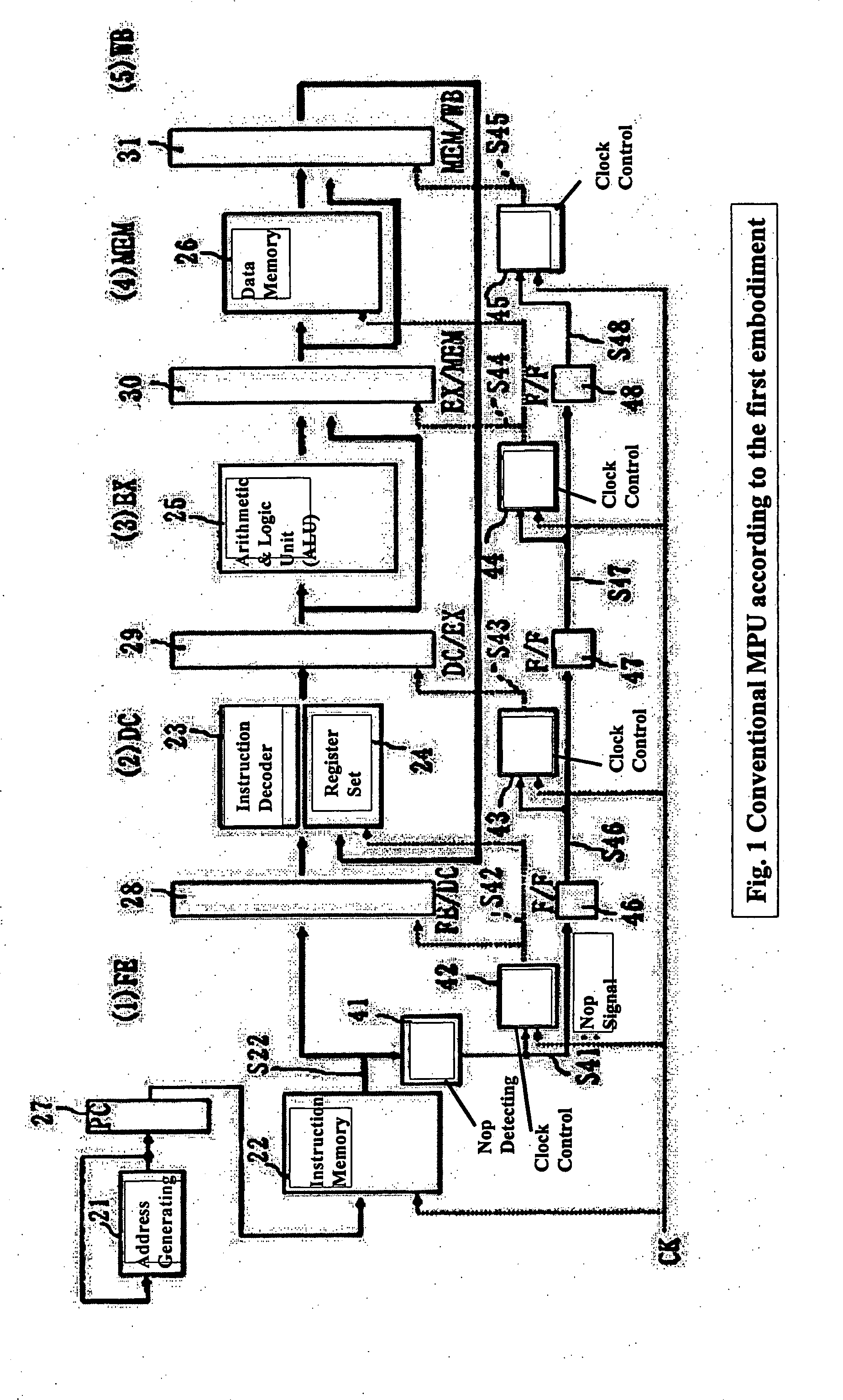
[0095]FIG. 1 is a view of general configuration diagram showing a configuration example of pipeline of a RISC-type MPU according to the first embodiment of the invention.

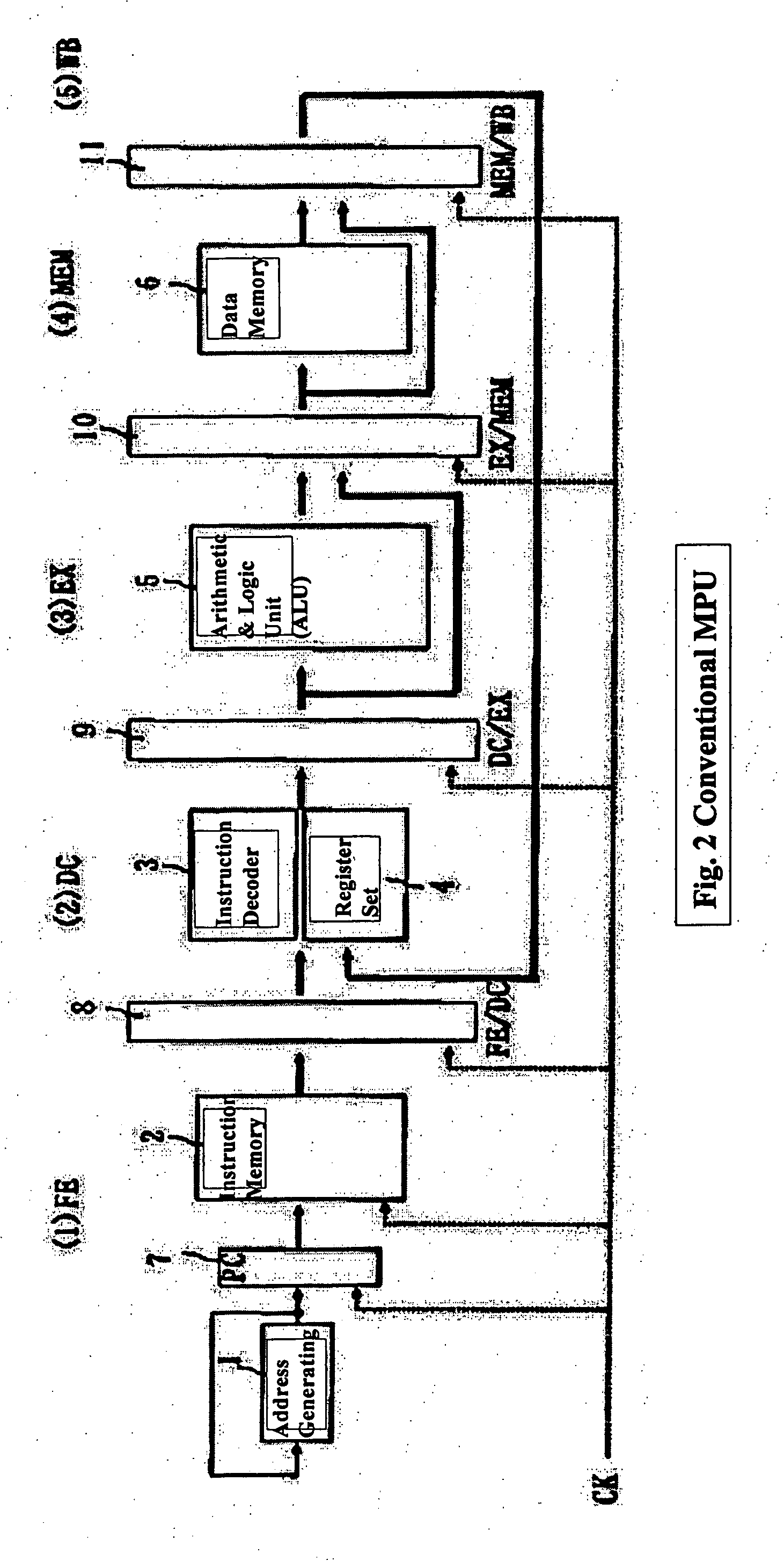
[0096]The above general configuration diagram shows an example of five-stage pipeline having the five stages of FE / DC / EX / MEM / WB as in the conventional case of FIG. 2.

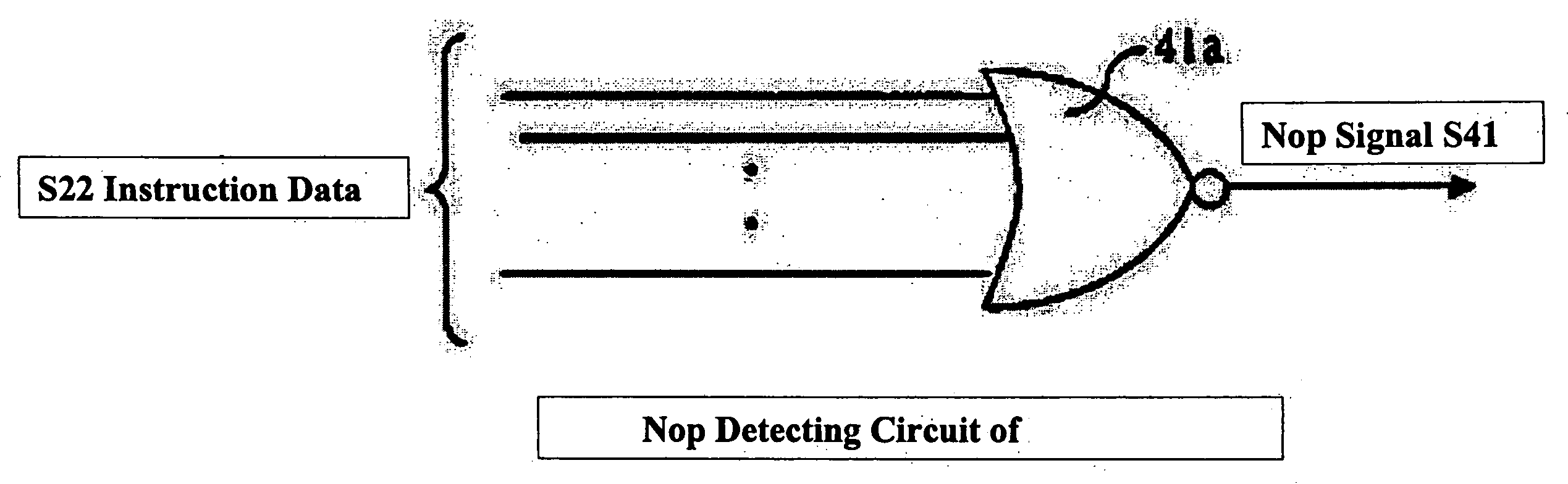
[0097]As in the conventional case of FIG. 2, the MPU according to the first embodiment includes a address generating register 21, an instruction memory 22, an instruction decoder 23, a register set 24, an arithmetic and logic unit (ALU) 25, and a data memory 26, and the MPU according to the first embodiment further includes a PC 27 between the address generating register 21 and the instruction memory 22, a FE / DC pipeline register 28 between the instruction memory 22 and the instruction decoder 23, a DC / EX pipeline register 29 between the instruction decoder 23 and the ALU 25 and between the register set 24 and the AL...

second embodiment

Configuration of the Second Embodiment

[0113]FIG. 6 is a view of general configuration diagram showing a configuration example of the RISC-type MPU according the second embodiment of the invention, and elements identical to ones in FIG. 1 of the first embodiment are given the same numerals as in FIG. 1.

[0114]The MPU according to the second embodiment is configured to include a nop-only bit S22a indicating logic level “H” in the case of the nop instruction, in the instruction data S22 outputted from the instruction memory 22 instead of the nop detecting circuit 41 according to the first embodiment, and is configured to input the above nop-only bit S22a directly to the clock control circuits 42 and the F / F 46 between the FE / DC stages. Other configurations are the same as in the first embodiment.

Operation of the Second Embodiment

[0115]In the case where the instruction data 522 fetched from the instruction memory 22 is the nop, the nop-only bit S22a is set to logic level “H” . Therefore...

third embodiment

Configuration of the Third Embodiment

[0118]FIG. 7 is a view of general configuration diagram showing a configuration example of the RISC-type MPU according to the third embodiment, and elements identical to ones in FIG. 6 of the second embodiment are given the same numerals.

[0119]The MPU according to the third embodiment includes;

[0120]an inverter 51 for inverting the clock CK;

[0121]an instruction memory 52 for outputting an instruction data S52 assigned by the address from the PC27 based on a gated clock S54;

[0122]an instruction memory 53 for outputting a nop-only bit S53 assigned by the address from the PC 27 based on the inverted clock;

[0123]a clock control circuit 54 for outputting a gated clock S54 based on the clock CK and the nop-only bit S53; and

[0124]a F / F 55 for inputting the nop-only bit S53 and outputting a nop signal S55 to the clock control circuit 42 and the F / F 46.

[0125]Other configurations thereof are the same as in the second embodiment.

[0126]In other words, the MP...


PUM


Abstract

Halting clocks of pipeline registers 28-31 and data memory 26, etc., and holding input data of each of FE, DC, MEM, WB stages, during when a nop is sent to each of pipelines, by a first process for outputting a nop signal S41 of logic level “H” when the nop is detected by a nop detecting circuit 41, a second process for sending the detected nop signal to each of the pipelines by F / Fs 46-48 placed between each of the pipelines, and a third process for halting clocks by clock control circuits 42-45 placed in each of the pipelines when the nop signal is sent to each of the pipelines.

Description

BACKGROUND OF THE INVENTION[0001]1. Field of the Invention[0002]The present invention relates to a RISC-type microprocessor (hereinafter referred to as “MPU”) adopting the pipeline configuration, one of speeding-up techniques, and especially relates to a technique for reducing the power consumption of the MPU thereof.[0003]2. Description of the Related Art[0004]A MPU is a semiconductor chip for basic computing within the computer. The computing of the MPU thereof has a computing flow as follows. First, the MPU reads programs stored in memories (memory devices), secondly, receives data from input devices or memories, etc., according to instructions of the programs and computes the data corresponding to the programs, then the MPU sends the data thereof to memories or displays (showing devices).[0005]Basic architecture of the above MPU is mainly divided to two types, the CISC architecture and the RISC architecture. The CICS architecture improves the computing throughput by increasing i...

Claims


Application Information

Patent Timeline
IPC IPC(8): G06F9/30G06F15/00G06F9/40
CPCG06F9/30079G06F9/3869G06F9/3867
Inventor GOKO, HIROKIMORIOKA, KENICHI
Owner LAPIS SEMICON CO LTD
Why Eureka
Try Eureka