Non-spheric eccentricity measuring method and device

A measuring device and aspheric surface technology, which is applied in the direction of measuring devices, optical devices, optical instrument testing, etc., can solve the problems of natural measurement accuracy limitations and other problems

Inactive Publication Date: 2003-05-28
OLYMPUS CORP
View PDF2 Cites 23 Cited by
  • Summary
  • Abstract
  • Description
  • Claims
  • Application Information

AI Technical Summary

Problems solved by technology

Therefore, due to the lack of proper adjustment, as a result, the improvement of measurement accuracy is limited

Method used


Image

  • Non-spheric eccentricity measuring method and device
  • Non-spheric eccentricity measuring method and device
  • Non-spheric eccentricity measuring method and device

Examples


no. 1 Embodiment

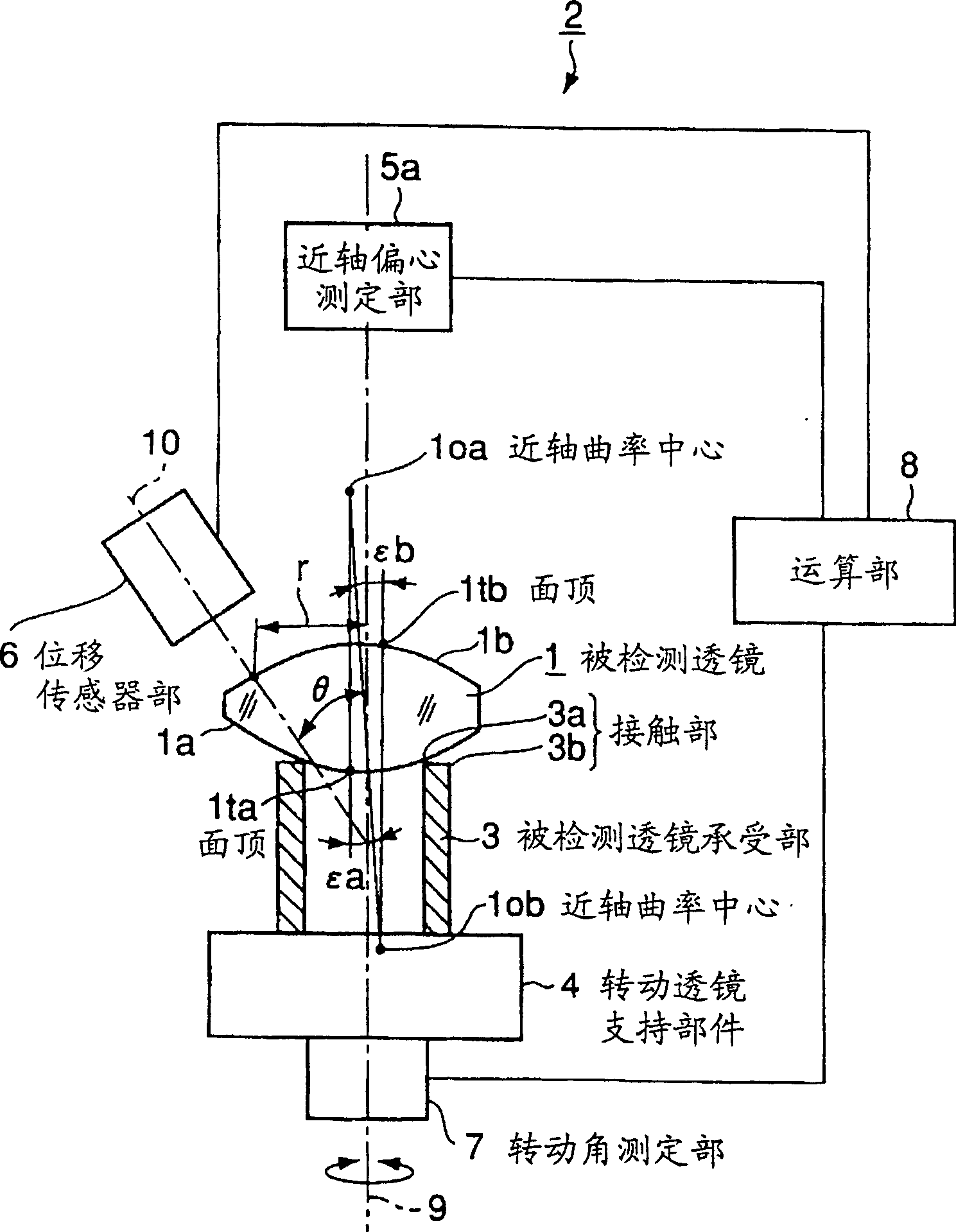
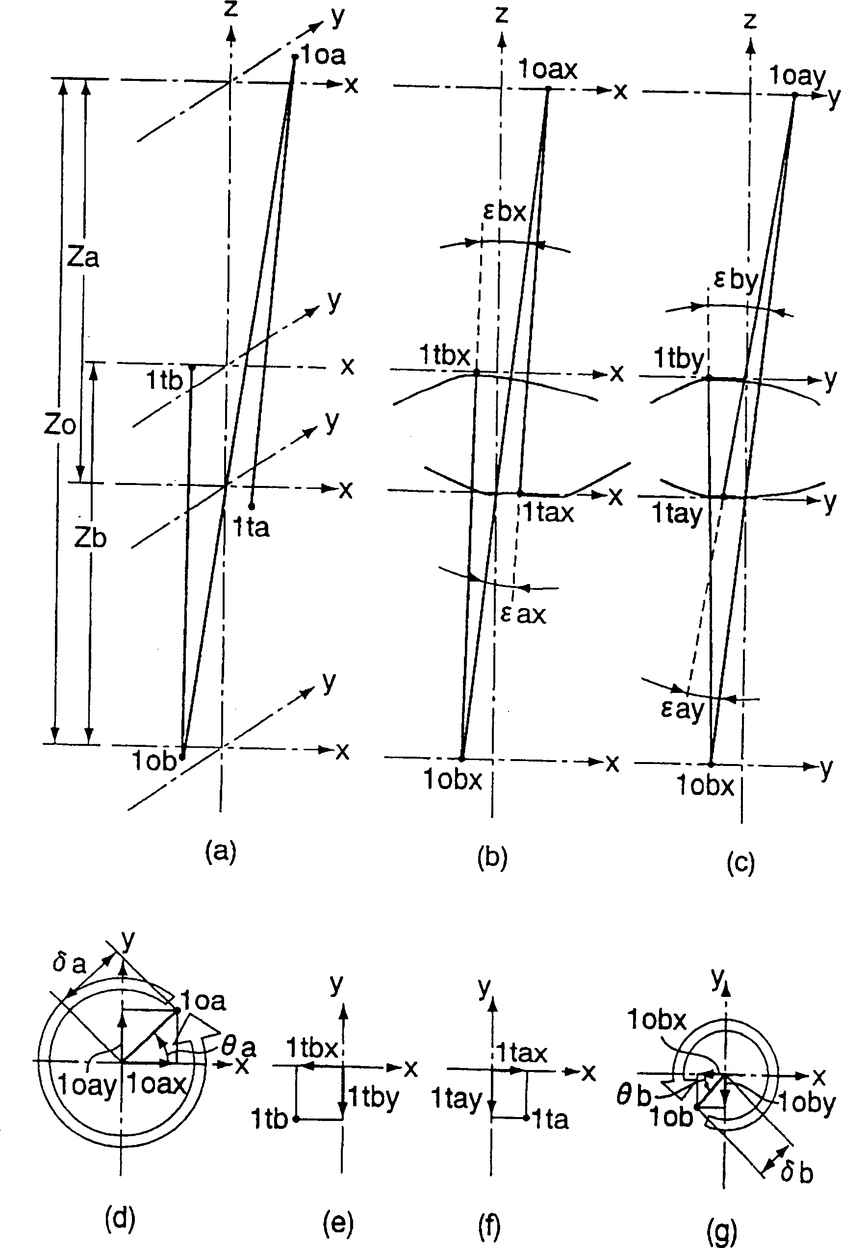
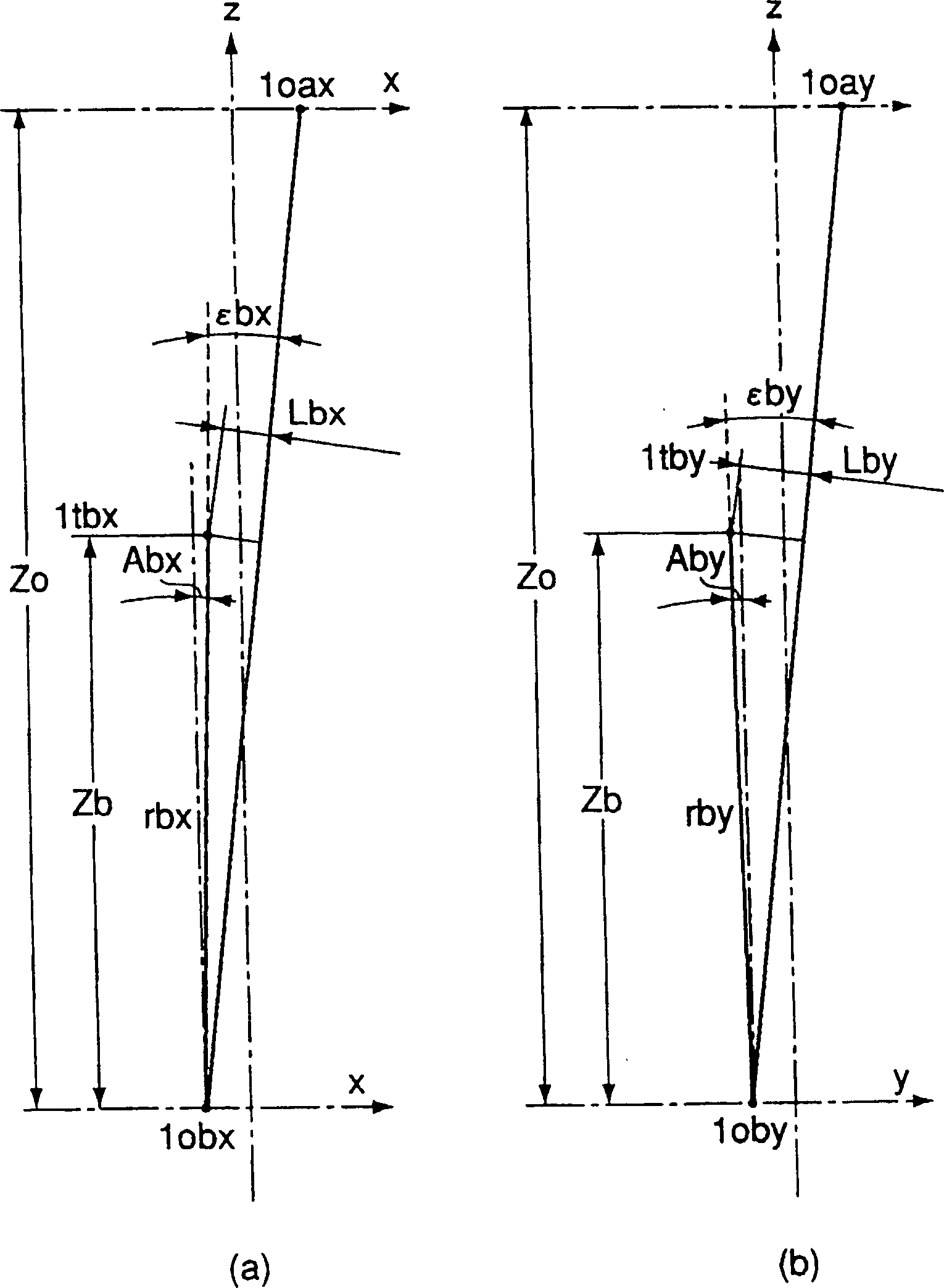
[0042] figure 1 shows the aspheric surface eccentricity measuring device as the first embodiment of the present invention, figure 2 and image 3 A detailed diagram showing the scheme when finding the eccentric value of an aspheric surface. Figure 4 The calculation procedure related to the measurement method of aspheric surface eccentricity is shown as a flow chart. exist figure 1 Among them, the aspheric lens eccentricity measuring device 2 is constituted as follows: the detected lens receiving part 3, which holds the measured object detected lens 1 rotatably; the rotating lens supporting member 4, which is used to rotate the detected lens receiving part 3; The measuring part 5 is used to detect the eccentricity of the paraxial curvature center of the two detected surfaces 1a and 1b of the detected lens 1 with respect to the rotation axis 9 of the rotating lens holding member 4; the detected surface shape measuring part (displacement sensor part) 6. It is used to detec...

Deformed example 1

[0153] exist Figure 5 In , a schematic configuration diagram of an aspheric surface eccentricity measuring device according to a modified example thereof is shown. As shown in the figure, if the detected surface shape measuring part (displacement sensor part) 6 is respectively arranged on the upper and lower sides of the detected lens 1, the inclination amount and direction of the aspheric axis of the receiving surface 1a can be detected without inversion. High-precision measurement of the eccentricity of the upper and lower aspheric surfaces.

[0154] More specifically, in Figure 5 Among them, the composition of the aspheric surface eccentricity measuring device 2 includes: the detected lens receiving part 3, which holds the detected lens 1 freely; the rotating lens supporting member 4, which is used to rotate the detected lens receiving part 3; , used to detect the eccentricity of the paraxial curvature center of the double-sided 1a and 1b of the detected lens 1 with res...

Deformed example 2

[0239] The first embodiment can also be modified and implemented as follows, and achieve the same or better effect than that of the first embodiment.

[0240] Figure 7 is a schematic configuration diagram showing an aspheric surface eccentricity measuring device according to the modification example.

[0241] As shown in the figure, the composition of the aspheric surface eccentricity measuring device 2 includes: a test lens receiving surface 3, which freely rotates to hold the test lens 1; a rotating lens support member 4, which is used to rotate the test lens shown in a vertical section The receiving part 3; the paraxial eccentricity measuring part 5a, which is used to detect the eccentricity of the paraxial curvature center of the reverse surface 1b of the receiving surface 1b of the detected lens 1 with respect to the rotation axis 9 of the rotating lens holding member 4 shown in a vertical section; The axial eccentricity measuring part 5b is used to detect the eccentric...


PUM


Abstract

The present invention provides a method for measuring easily and with high accuracy the amount and the direction of decentering of an aspherical surface of an aspherical lens and a device for measuring them. The measuring device comprises: a lens receiving part; a rotating lens supporting member; a paraxial decentering measuring part, detecting the amount and direction of the decentering of a paraxial focus of both faces of the lens to be detected, relative to an axis of rotation of the member for supporting the rotating lens; a shape measuring part for a surface to be detected, detects the shape of the surface to be detected; a rotational angle measuring part, detecting the rotational angle of the lens to be detected; and an arithmetic part. In the arithmetic part, data, which is obtained by the part for measuring the shape of the surface to be detected by rotating the lens to be detected, is compared with design formulas of the surface to be detected, and the amount of relative shift and tilt, which make difference of them to be the smallest, are calculated. A position of the top of the surface relative to the axis of the rotation is calculated from the amount of the shift and tilt. The amount of the tilt and the direction of an aspherical axis relative to an optical axis of the lens to be detected, are calculated from the position of the top of the surface and the amount and direction of the decentering of the paraxial focus of the both faces of the lens to be detected, measured by the parts for measuring the paraxial decentering.

Description

technical field [0001] The invention relates to an aspheric lens eccentricity measuring device and an aspheric eccentricity measuring method for measuring the inclination of the aspheric axis of the aspheric lens, wherein the aspheric lens includes a double-sided aspheric lens and a single-sided aspheric lens. Background technique [0002] As a measurement technique for inspecting decentering of an aspheric lens, in recent years, for example, JP-A-7-159288 discloses a decentering measuring device for an aspheric lens and a decentering measuring method thereof. use Figure 8 (a) to (e) illustrate the existing aspheric lens decentration measurement method, according to Figure 9 An outline of a conventional aspheric lens decentering measuring device for realizing this method will be described. [0003] first in Figure 8 (a) shows an example of a lens having aspheric surfaces on both surfaces. The double-sided aspheric surfaces 1b, 1a indicated by the solid lines of the asph...

Claims


Application Information

Patent Timeline
Patent Type & Authority Applications(China)
IPC IPC(8): G01B11/27G01B11/00G01B11/24G01M11/00
Inventor 泉田丰
Owner OLYMPUS CORP
Why Eureka
Try Eureka