
Adjustable lens group apparatus

A mirror group and lens technology, which is applied in the field of adjustable mirror group devices, can solve problems such as non-coplanar skew when the transmission cannot be effectively adjusted

Inactive Publication Date: 2003-06-11
IND TECH RES INST
View PDF3 Cites 3 Cited by
  • Summary
  • Abstract
  • Description
  • Claims
  • Application Information

AI Technical Summary

Problems solved by technology

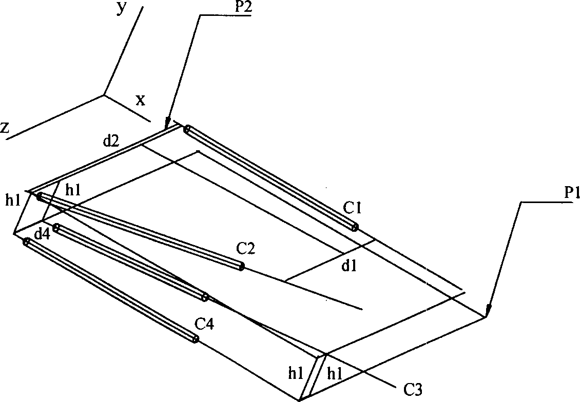
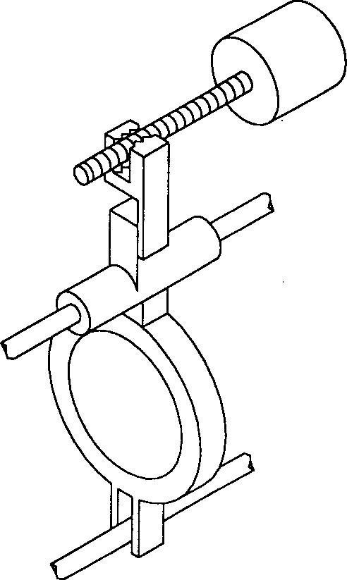
[0008] The object of the present invention is to provide an adjustable mirror group device, which is a mirror group moving mechanism with multi-degree-of-freedom adjustment function, so as to solve the above-mentioned skew problem that cannot be effectively adjusted when the transmission is not coplanar

Method used


Image

  • Adjustable lens group apparatus
  • Adjustable lens group apparatus
  • Adjustable lens group apparatus

Examples


Embodiment Construction

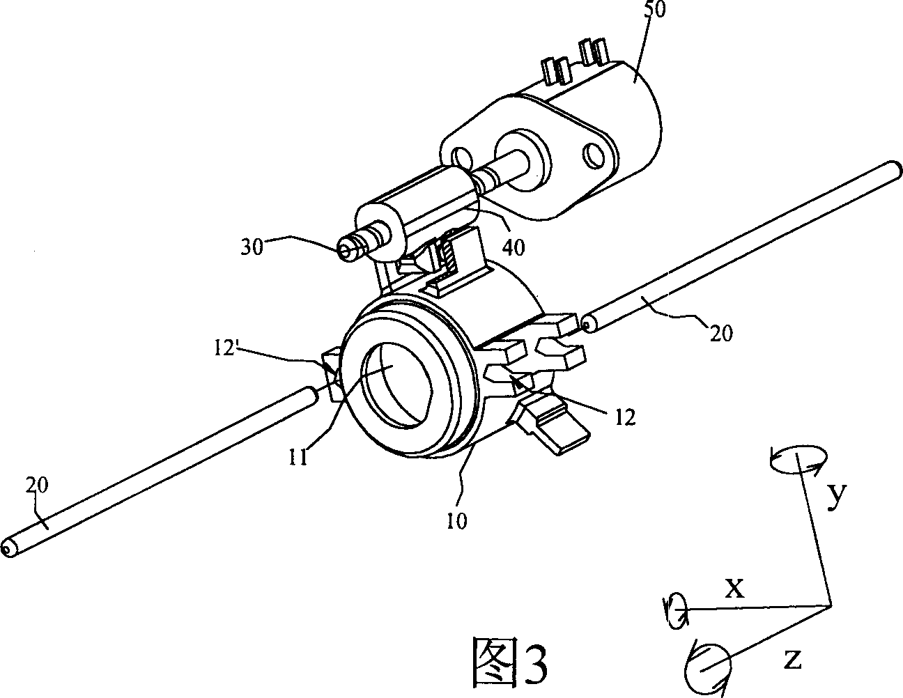
[0041] The adjustable mirror group device of the present invention is a mirror group moving mechanism with a multi-degree-of-freedom adjustment function, to solve the above-mentioned problems, by providing a connecting and engaging mechanism in the mirror group moving mechanism, the driver and the mirror group can be adjusted at any time The position and direction of the driving screw, the driving member and the mirror group are such that even when the driving screw and the optical axis or the guide member (such as a guide rod) are skewed, the mirror group can move smoothly along the optical axis.

[0042] As shown in Figure 3, Figure 4As shown, the adjustable lens group device proposed by the present invention includes a lens group barrel 10, at least one guide member 20, a driving screw 30, a driving member 40, etc.; wherein the driving member 40 is engaged with the driving screw 30 and is The driving screw 30 rotates to make the driving lens group barrel 10 move along the ...


PUM


Abstract

The device comprises the lens cluster barrel, the guidance assembly, the driving screw and the drive piece. The central axis of the guidance assembly parallel to the optical axis of the lens cluster barrel is utilized to drive the motion of the lens cluster barrel. The driven piece through the interlock of the driving screw drives the motion of the lens cluster barrel along the direction parallel to the optical axis. The movable combination relation is formed between the driven piece and the lens cluster barrel through the connection piece. Thus, the drive piece possesses the function for adjusting the directions of multiple degrees of freedom. In the case of not parallel inclined relation between the driving screw and the optical axis, the direction of the drive piece can be adjusted so as to make the lens cluster barrel move smoothly.

Description

technical field [0001] The invention relates to an adjustable mirror group device, which is applied to the imaging lens of equipment such as cameras, video recorders, and monitoring systems. In particular, a lead screw mechanism is used to drive the mirror group to move, so as to achieve the focus of the mirror group or a lens group device for purposes such as zooming. Background technique [0002] For lens module design, in the past, in order to meet the miniaturization requirements of the entire lens volume, a lead screw mechanism is usually used to drive the movement of the lens group to achieve the purpose of focusing or zooming the lens group. [0003] However, in the lead screw mechanism, great attention must be paid to the parallel relationship between the drive screw and the guide part, otherwise it is easy to cause errors in manufacturing and assembly, resulting in the axis of the drive screw or the distance between the drive part and the guide part. Distortion occ...

Claims


Application Information

Patent Timeline
Patent Type & Authority Applications(China)
IPC IPC(8): G02B15/14
Inventor 涂银发姜皇成陈志文张耿智
Owner IND TECH RES INST
Learn More