Printing ink box and printing machine

A technology of ink cartridges and printing tapes, applied in printing and other directions, can solve the problems of low installation efficiency and complicated installation, and achieve the effect of simple and convenient installation methods.

Pending Publication Date: 2019-12-13
XIAMEN HANIN ELECTRONICS TECH CO LTD
View PDF0 Cites 0 Cited by
  • Summary
  • Abstract
  • Description
  • Claims
  • Application Information

AI Technical Summary

Problems solved by technology

The printing belt assembly 2' assembled in this way is complicated to install, which leads to low installation efficiency, and the printing belt assembly 2' as a consumable, needs to be connected with the printing belt assembly 2 when the printing belt 21' is used up and needs to be replaced. 'Scrap together with cassette body 11' and reinstall new ribbon assembly cassette 1' with ribbon 21'

Method used


Image

  • Printing ink box and printing machine
  • Printing ink box and printing machine
  • Printing ink box and printing machine

Examples


no. 1 example

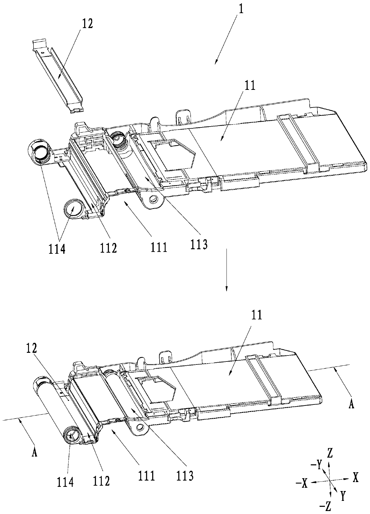
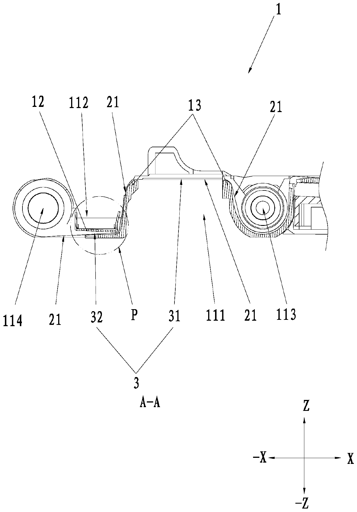
[0039] An implementation of the present invention provides a printing ink cartridge 1 which can be used for loading and fixing a printing ribbon assembly 2 . combine figure 2 , image 3As shown, the box body 1 includes a frame 11 . The frame 11 has a feeding channel, a U-shaped area 111 and a U-shaped groove 112 . Wherein, the U-shaped region 111 has a first opening facing the negative direction side of the second direction, and the U-shaped groove 112 has a second opening facing the positive direction side of the second direction. The U-shaped groove 112 has a pressing device in the second direction. In this embodiment, the pressing device is a pressing plate 12 . The bottom of the U-shaped area 111 is provided with a tension portion 13 . The feeding path 3 includes a first path 31 and a second path 32 connected to the first path 31 . Viewed from the first direction, along the second direction, the first path 31 is located on the positive direction side of the tensionin...

no. 2 example

[0043] Based on the first embodiment, in the second embodiment, combining Figure 4 The pressing plate 12 includes a base plate 51 and guide portions 52 located at both ends of the base plate 51 along the first direction. combine Figure 5 , the guide portion 52 extends along the positive side of the second direction. The substrate 51 has the second path 32 along the negative direction side of the second direction. A guide portion 52 between the first path 31 and the second path 32 forms a third path 33 for communicating with the first path 31 and the second path 32 on a side away from the other guide portion 52 . Wherein, the arc segment between the base plate 51 and the guide portion 52 is transitionally connected. It can be understood that the guide portion 52 can be used as a baffle to separate the U-shaped groove 112 from the printing belt assembly 2 .

[0044] In a second embodiment, combining Figure 5 , the bottom of the pressing plate (that is, the base plate 51 ...

no. 3 example

[0048] Based on the second embodiment, in the third embodiment, combining Figure 7 , the first end of the pressing plate 12 along the third direction has a first fastening member 43, the first fastening member 43 includes a first clamping portion 431 and a second clamping portion 432, the first clamping portion 431 and the second clamping portion The second clamping portion 432 is formed at a first end of the substrate 51 along the third direction, and the first end is an end of the substrate 51 on the positive side of the third direction. The second clamping portion 432 is formed and supported on the first clamping portion 431 , and the first clamping portion 431 and the second clamping portion 432 are arranged at intervals along the second direction. Along the second direction, a clamping groove 433 is sandwiched between the first clamping portion 431 and the second clamping portion 432 .

[0049] In a third embodiment, combining Figure 8 , there is a second fastening me...


PUM


Abstract

The invention relates to a printing ink box. The printing ink box comprises a framework, a type belt storage bin and a type belt recycling bin are arranged on the framework, and a type belt passes through a first path and a second path between the type belt storage bin and the type belt recycling bin. The printing ink box is characterized in that the first path and the second path are arranged onthe framework in a staggered floor mode. The printing ink box further comprises a pressing device, and the first path or the second path is formed by detachably fixing the pressing device to the framework. The invention further provides a printing machine with the printing ink box.

Description

technical field [0001] The invention relates to the technical field of printers, in particular to a print cartridge and a printer. Background technique [0002] Now, portable printers are widely used in shopping malls, retail stores or homes. There are many types of portable printers, including inkjet, thermal, thermal transfer, electrostatic and other printers according to the technology used. Wherein, thermal transfer printing equipment needs to use a printing ribbon assembly box, and the printing ribbon assembly box includes a box body, a supply roll fixed on the box body, a recovery shaft, and a printing tape whose two ends are connected to the two rolls. [0003] In the prior art, refer to figure 1 , the printing ink cartridge 1' is integrally formed, and then the printing tape 21' that is not connected to one of the rolls at least one end passes through the reversing hole S1', and then the unfixed end of the printing tape 21' is wound and supported on the box body 11...

Claims


Application Information

Patent Timeline
Patent Type & Authority Applications(China)
IPC IPC(8): B41J2/01B41J2/175
CPCB41J2/01B41J2/17503
Inventor 不公告发明人
Owner XIAMEN HANIN ELECTRONICS TECH CO LTD
Why Eureka
Try Eureka