Image sense component and optical machine mobule using said image sense component

A technology of image sensing and optical-mechanical modules, applied in image communication, electrical components, etc., can solve the problem of increased image scanning time

Inactive Publication Date: 2003-09-24
AVISION PRECISION IND (SUZHOU) CO LTD
View PDF0 Cites 1 Cited by
  • Summary
  • Abstract
  • Description
  • Claims
  • Application Information

AI Technical Summary

Problems solved by technology

With only one image sensor, the time required for all electronic signals to fully transmit increases, so the image scanning time increases, which is a design disadvantage for large scanners

Method used


Image

  • Image sense component and optical machine mobule using said image sense component
  • Image sense component and optical machine mobule using said image sense component
  • Image sense component and optical machine mobule using said image sense component

Examples


Embodiment Construction

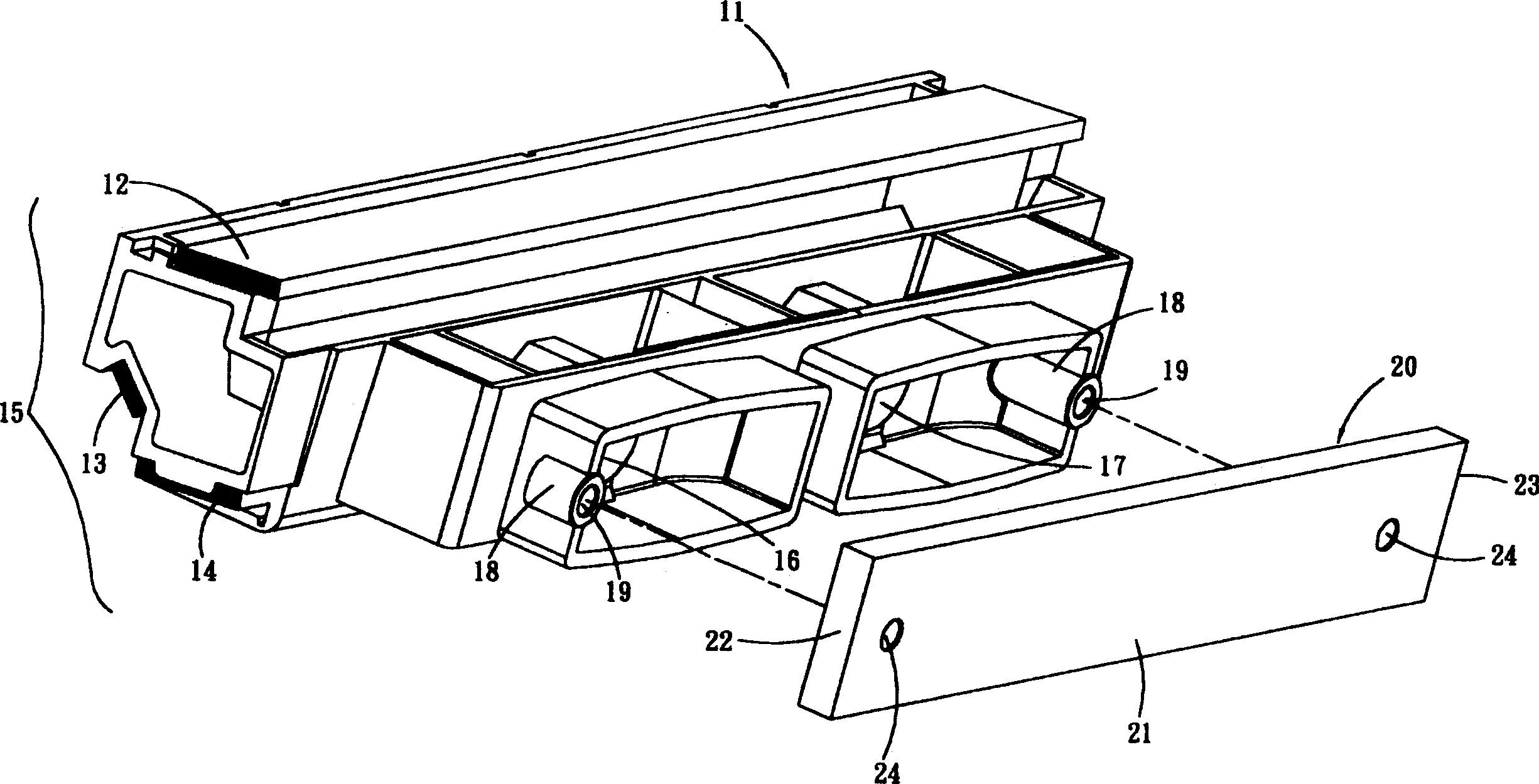
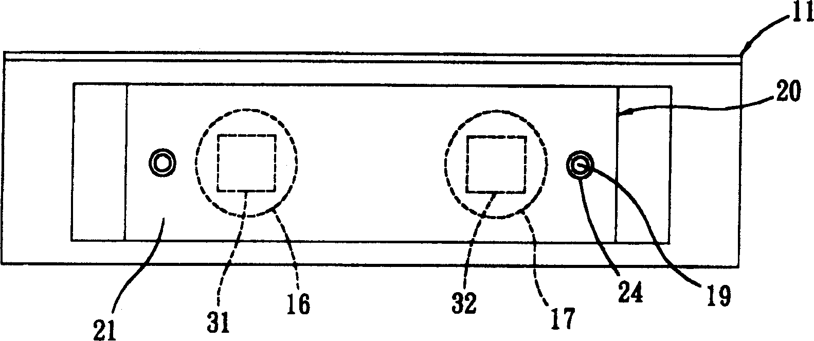
[0011] Such as figure 1 Shown is an exploded view of the optical-mechanical module of the present invention. The figure shows that the optical-mechanical module includes an optical-mechanical base 11 and an image sensing component 20 . The image sensing component 20 includes a sensing component seat 21 . Several mirrors 12 , 13 , 14 are assembled on the optical machine base 11 , and the several mirrors 12 , 13 , 14 are called mirror group 15 . At least two lenses 16 , 17 are arranged on the optical base 11 in a direction away from the mirror group 15 .

[0012] The image sensor assembly 20 is set on the optical base 11, away from the mirror assembly 15 and corresponding to the two lenses 16, 17, for receiving image information.

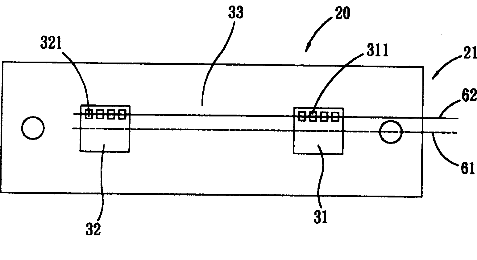
[0013] Such as figure 2 Shown is a schematic plan view of the image sensing component 20 . The sensing component seat 21 of the image sensing component 20 corresponds to the surface of the reflective lens (not shown), and at least two image sens...


PUM


Abstract

An image sensing component includes a component sent and several image sensors containing several sensing pels array in a same direction with that of the image sensors. The above mentioned image sensors are fixed on the sensing components, the adjacent image sensors are aligned with each other in distance, therefore when the above mentioned image sensing components are mounted on a photo module, the image sensors are not tilted nor offset oppositing to the position of the photo seat to solve the problem of tilt of every image sensor to related photo seat.

Description

technical field [0001] The present invention relates to an image sensing component and an optomechanical module using the same, in particular to an image sensing component with multiple image sensors arranged in a straight line and an optomechanical module using the image sensing component . Background technique [0002] In the application of general-sized scanners, several image sensors can be used to receive image information, so as to shorten the total optical path of each optical-mechanical module, reduce the cost of lenses, assembly costs of mirrors, and the cost of the whole scanner. In the application of large scanners, several image sensors are usually used to receive image information. Since the image information received by each image sensor comes from each section of a large file, the images of each section must be further combined by image stitching technology. When there is an error in the relationship between several image sensors, comple...

Claims


Application Information

Patent Timeline
IPC IPC(8): H04N1/047
Inventor 盛少澜
Owner AVISION PRECISION IND (SUZHOU) CO LTD
Why Eureka
Try Eureka