Laser beam spot shape correcting method

A correction method, laser beam technology, applied in laser welding equipment, optics, condenser mirrors, etc., can solve the problem of time-consuming correction of spot shape, achieve the effect of suppressing man-hours and reducing mechanical errors

Pending Publication Date: 2021-06-11
DISCO CORP
View PDF1 Cites 2 Cited by
  • Summary
  • Abstract
  • Description
  • Claims
  • Application Information

AI Technical Summary

Problems solved by technology

[0007] However, in the technology shown in Patent Document 2, even if the shape of the spot can be grasped, it is not known where the optical deformation occurs among the plurality of optical elements constituting the optical system. Therefore, it is necessary to specify the location of the deformation, and there is a problem with the shape of the spot. Correcting time-consuming issues

Method used


Image

  • Laser beam spot shape correcting method
  • Laser beam spot shape correcting method
  • Laser beam spot shape correcting method

Examples


no. 1 Embodiment approach 〕

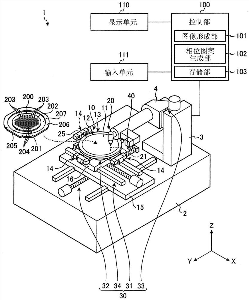
[0049] The method of correcting the spot shape of the laser beam according to the first embodiment of the present invention will be described with reference to the drawings. First, the configuration of the laser processing apparatus 1 for implementing the method of correcting the spot shape of the laser beam according to the first embodiment will be described. figure 1 It is a perspective view showing a configuration example of a laser processing apparatus implementing the method of correcting the spot shape of a laser beam according to the first embodiment. of the first embodiment figure 1 The illustrated laser processing apparatus 1 is an apparatus that irradiates a workpiece 200 with a pulsed laser beam 21 to perform laser processing on the workpiece 200 .

[0050] as figure 1 The workpiece 200 to be processed by the illustrated laser processing apparatus 1 is a wafer such as a disc-shaped semiconductor wafer or an optical device wafer having a substrate 201 of silicon, s...

no. 2 Embodiment approach 〕

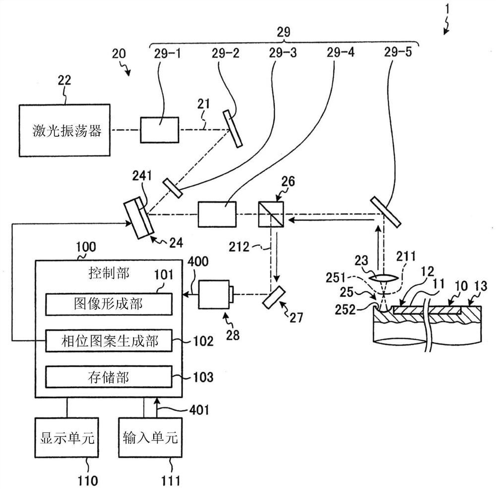
[0112] A method of correcting a spot shape of a laser beam according to a second embodiment of the present invention will be described with reference to the drawings. Figure 15 It is a perspective view showing a configuration example of a laser processing apparatus implementing the method of correcting the spot shape of a laser beam according to the second embodiment. Figure 16 is true Figure 15 A diagram illustrating the structure of the laser beam irradiation unit of the laser processing apparatus shown. In addition, in Figure 15 and Figure 16 In the description, the same reference numerals are attached to the same parts as those in the first embodiment, and description thereof will be omitted.

[0113] In addition to the functions of the image forming unit 101-2 and the storage unit 103-2, the laser processing apparatus 1-2 implementing the method of correcting the spot shape of the laser beam (hereinafter referred to as the correction method) according to the secon...


PUM


Abstract

The invention provides a laser beam spot shape correcting method, which can restrain the working hours required for correcting the spot shape of the laser beam and can reduce the mechanical error between processing devices of the laser beam irradiated to a processed object. The laser beam spot shape correcting method includes a laser beam irradiating step of irradiating a concave mirror with a laser beam, an imaging step of imaging reflected light by a beam profiler, an image forming step of forming an XZ plane image or a YZ plane image from an XY plane image imaged in the imaging step, and a comparing step of comparing the image formed in the image forming step with an XZ plane image or a YZ plane image of an ideal laser beam. A phase pattern displayed on a display unit of a spatial light modulator is changed such that the XZ plane image or the YZ plane image formed in the image forming step coincides with the XZ plane image or the YZ plane image of the ideal laser beam.

Description

technical field [0001] The invention relates to a method for correcting the spot shape of a laser beam. Background technique [0002] As a technique for dividing a plate-like object such as a semiconductor wafer into chip sizes, there is known a technique in which the focus of a laser beam is positioned inside the workpiece and irradiated along the planned division line to form a modified layer (for example, refer to Patent Document 1). [0003] However, various optical components are used in the optical system of a laser processing apparatus that performs laser processing as described above, and various optical distortions may occur on the optical path of the optical system. Due to this optical distortion, processing results may differ among processing devices, and a so-called inter-device mechanical error may occur. [0004] In order to solve this problem, a technique has been proposed in which the concave mirror is held by a chuck table and the light reflected from the ...

Claims


Application Information

Patent Timeline
Patent Type & Authority Applications(China)
IPC IPC(8): B23K26/064B23K26/042B23K26/03B23K26/53
CPCB23K26/064B23K26/042B23K26/032B23K26/53B23K26/0648B23K26/0643B23K26/073B23K26/03B23K26/70B23K26/705H01L21/67092G02F1/136277G02B19/0052G02B19/0028G02B27/0068G02B27/0944G02B27/0927G02B5/10G02B26/0816B23Q3/06H01L22/20B23K2103/56G02B19/0085H01L21/67115H01L21/67253H01L21/268H01L21/78G02F2203/50G02F2203/12G02B19/0009
Inventor 植木笃野村哲平
Owner DISCO CORP
Why Eureka
Try Eureka