
Step motor

A stepping motor and rotating shaft technology, applied in electrical components, electromechanical devices, etc., can solve the problems of destroying the magnetic distribution of the fixed magnet rotor, the influence of the rotating speed and torque of the fixed magnet rotor, and reducing the working efficiency of the stepping motor.

Inactive Publication Date: 2003-07-02
UMAX DATA SYST
View PDF0 Cites 0 Cited by
  • Summary
  • Abstract
  • Description
  • Claims
  • Application Information

AI Technical Summary

Problems solved by technology

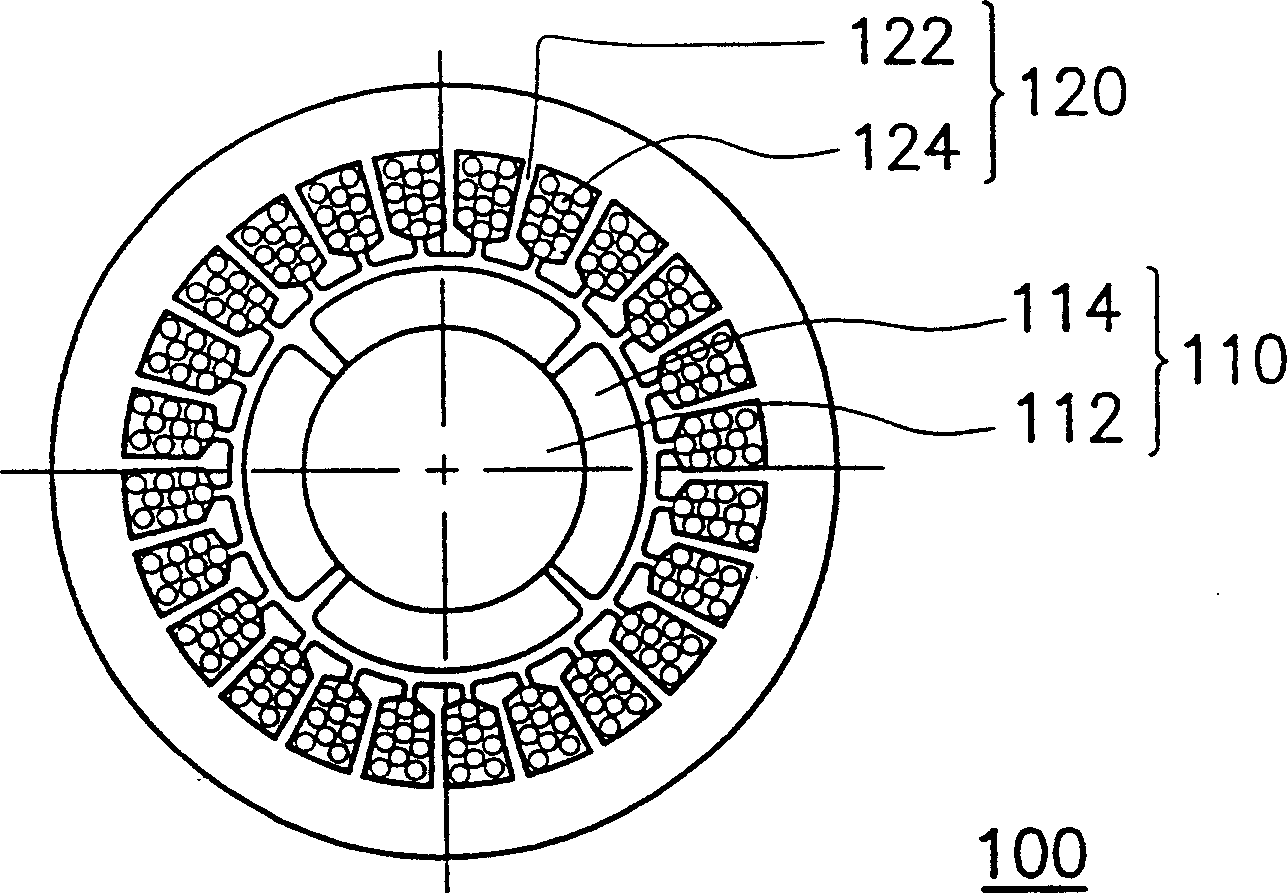
[0004] Most of the known stepping motors use a fixed magnet rotor (that is, a rotor with permanent magnets as salient poles) and a variable magnet stator (that is, a stator that generates a magnetic field with an input current to the armature coil). After the magnetization is completed, the size of its magnetic flux is fixed. Therefore, the known stepping motor may destroy the original magnetic distribution of the fixed magnet rotor after long-term use or when the temperature is too high. Under the action of the magnetic field, it is easy to affect the speed and torque of the fixed magnet rotor, thus reducing the overall working efficiency of the stepping motor

Method used


Image

  • Step motor
  • Step motor
  • Step motor

Examples


no. 1 example

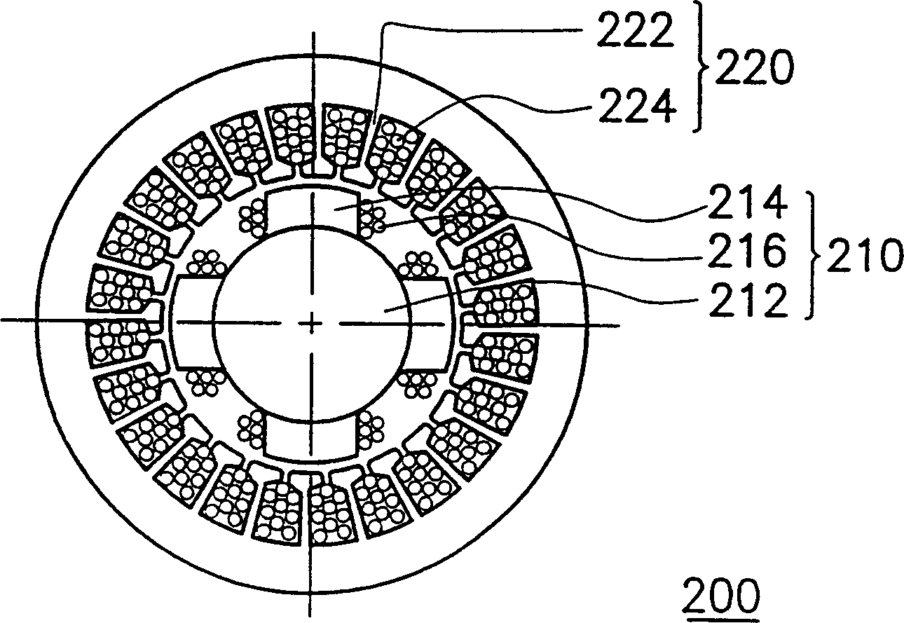
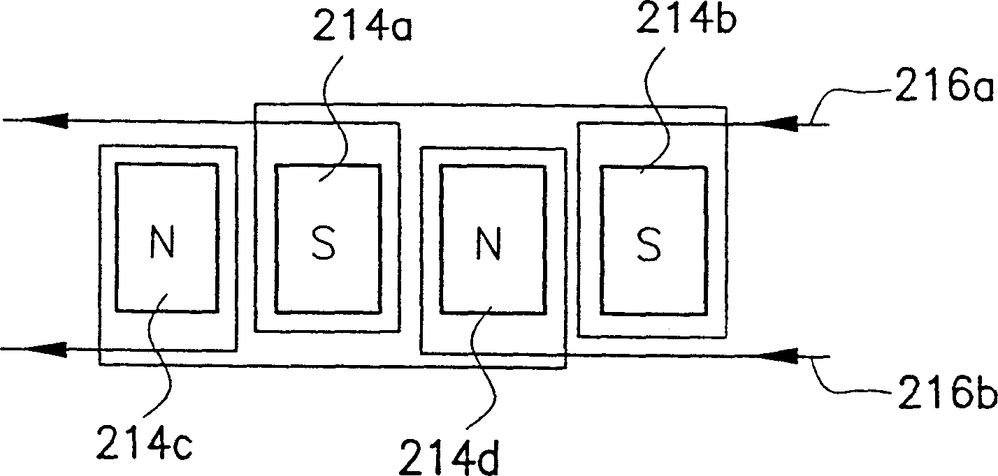
[0036] Please refer to figure 2 , which is a schematic cross-sectional view of the stepping motor according to the first embodiment of the present invention. The stepping motor 200 is mainly composed of a rotor 210 and a stator 220 . The rotor 210 is composed of a rotating shaft 212, a plurality of salient poles 214 and a plurality of electromagnetic coils 216, wherein the salient poles 214, such as N poles or S poles of a permanent magnet, surround the rotating shaft 212 in turn and protrude from the diameter of the rotating shaft 212 respectively. Towards. It should be noted that the electromagnetic coils 216 are respectively wound on one of the salient poles 214 in the radial direction of the rotating shaft 212 . The stator 220 is composed of a plurality of armature cores 222 and a plurality of armature coils 224, wherein a space is reserved between two adjacent armature cores 222, so that each group of armature coils 224 can be wound on one armature core 222 , and each...

no. 2 example

[0041] The difference between the second embodiment of the present invention and the first embodiment lies in the winding position and the winding direction of the electromagnetic coil. Please refer to Figure 4 , which is a schematic longitudinal cross-sectional view of a stepping motor according to the second embodiment of the present invention.

[0042] The stepping motor 300 is mainly composed of a rotor 310 and a stator 320 . The rotor 310 is composed of a rotating shaft 312, a plurality of salient poles 314 and at least one electromagnetic coil 316a, wherein the salient poles 314, such as N poles or S poles of a permanent magnet, surround the rotating shaft 312 in turn and protrude from the diameter of the rotating shaft 312 respectively. Towards. It should be noted that the electromagnetic coil 316 a is wound on the rotating shaft 312 in the axial direction of the rotating shaft 312 . The stator 320 is composed of a plurality of armature cores 322 and the armature coil...


PUM


Abstract

A step motor has a rotor and a stator. Said rotor is composed of a shaft with multiple salient poles on its surface, multiple groups of electromagnetic windings wound on salient poles and at least one electromagnetic winding wound on shaft. Said stator consists of multiple armature cores surrounding rotor and multiple groups of armature windings wound on armature cores.

Description

technical field [0001] The present invention relates to a stepping motor (stepping motor or stepper motor), in particular to an electromagnetic coil wound on the salient poles of the rotor, or an electromagnetic coil wound on the salient poles of the rotor in the axial direction of the rotating shaft. the stepper motor. Background technique [0002] In many industrial control systems, precise positioning or speed control of a workpiece is required, and stepping motors (stepping motors or stepper motors) are suitable for such applications. Because of the advantages of light weight, concealment, high efficiency, good control performance, and maintenance-free, stepping motors are widely used as power sources for image input and output devices such as scanners, printers, fax machines, and copiers. [0003] Please refer to figure 1 , which is a schematic cross-sectional view of a known stepping motor. The stepping motor 100 is mainly composed of a rotor (rotor) 110 and a stato...

Claims


Application Information

Patent Timeline
IPC IPC(8): H02K37/00H02K37/10
Inventor 郭士文
Owner UMAX DATA SYST
Learn More