Communication system

A communication system and a technology for selecting information, which is applied in the field of communication systems providing virtual private network services, and can solve problems such as business congestion, long-term interruption of communication services, and data loss

Inactive Publication Date: 2003-07-23
FUJITSU LTD
View PDF0 Cites 8 Cited by
  • Summary
  • Abstract
  • Description
  • Claims
  • Application Information

AI Technical Summary

Problems solved by technology

Otherwise, a single link failure will cause a long-term interruption of communication services, and business congestion problems will cause delays or loss of data

Method used


Image

  • Communication system
  • Communication system
  • Communication system

Examples


Embodiment Construction

[0042] Hereinafter, preferred embodiments of the present invention will be described with reference to the drawings.

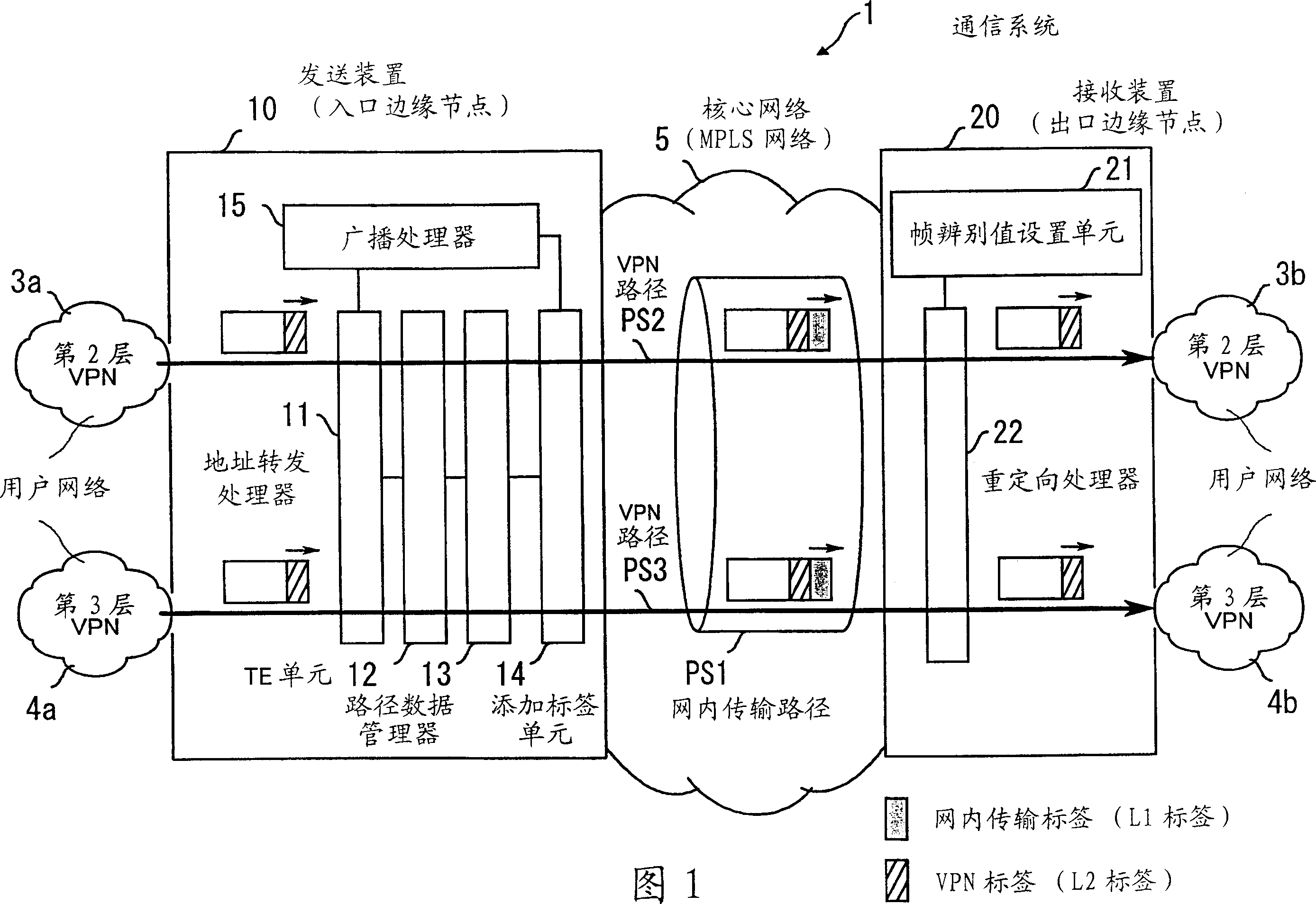
[0043] Fig. 1 is a conceptual diagram of the communication system of the present invention. The illustrated communication system 1 includes a transmitting device 10 and a receiving device 20. Hereinafter, the sending device 10 is referred to as an ingress edge node 10, and the receiving device 20 is referred to as an egress edge node 20. Two nodes 10 and 20 are located at the end of the core network 5. The core network is an MPLS network with multi-protocol label switching capabilities. The proposed system is used in the MPLS-VPN environment.

[0044] The ingress edge node 10 is connected to a layer 2 VPN 3a and a layer 3 VPN 4a serving as a user network. Likewise, the egress edge node 20 is connected to the layer 2 VPN 3b and the layer 3 VPN 4b. Although Fig. 1 shows the proposed ingress edge node 10 and egress edge node 20 as separate entities, if appropriate, t...


PUM


Abstract

A communications system in which both a layer-2 and layer-3 virtual private networks (VPNS) can operate in an efficient and cost-effective way to offer improved network services. An ingress edge node has a path data manager which sets and manages path data describing configuration of an intra-network transport path. For transport over the intra-network transport path, a labeling unit adds an intra-network transport label to each outgoing frame, based on the path data. Those frames also have a VPN label for transport over an end-to-end VPN path. In an egress edge node, a frame discrimination value setting unit gives a frame discrimination value for identifying to which VPN each received frame belongs. A redirection processor redirects the received frames to their destinations according to their VPN labels and frame discrimination value.

Description

Technical field [0001] The present invention relates to a communication system, in particular to a communication system that provides virtual private network services. Background technique [0002] A new type of network service called "Virtual Private Network" (VPN) has been developed in recent years. VPN collectively involves such services: by merging a part of other people's networks (for example, telephone company or Internet provider's network) to allow us to connect and expand our private network, as an alternative to leased line services. Using VPN technology, a company with many offices throughout the country can build a large private network by interconnecting their local area network (LAN) with the Internet. Generally speaking, VPNs are roughly divided into two groups, one group is based on layer 3 (network layer), and the other group is based on layer 2 (data link layer). [0003] FIG. 27 shows the structure of a VPN 400 (hereinafter referred to as "layer 3 VPN") operat...

Claims


Application Information

Patent Timeline
Patent Type & Authority Applications(China)
IPC IPC(8): H04L12/46H04L45/247H04L45/50
CPCH04L45/507H04L45/22H04L45/50H04L12/4675H04L49/3009H04L47/125H04L45/28H04L49/201H04L45/00H04L45/24H04L49/602H04L45/76
Inventor 山田浩堀之内义章中松亮二石井贤一
Owner FUJITSU LTD
Why Eureka
Try Eureka