

Inverse projection method and computerized X-ray tomographic device
A back-projection, X-ray technology, applied in the field of X-ray CT devices, can solve complex, time-consuming and other problems
- Summary
- Abstract
- Description
- Claims
- Application Information
AI Technical Summary
Problems solved by technology
Method used
Image

Examples
no. 1 example
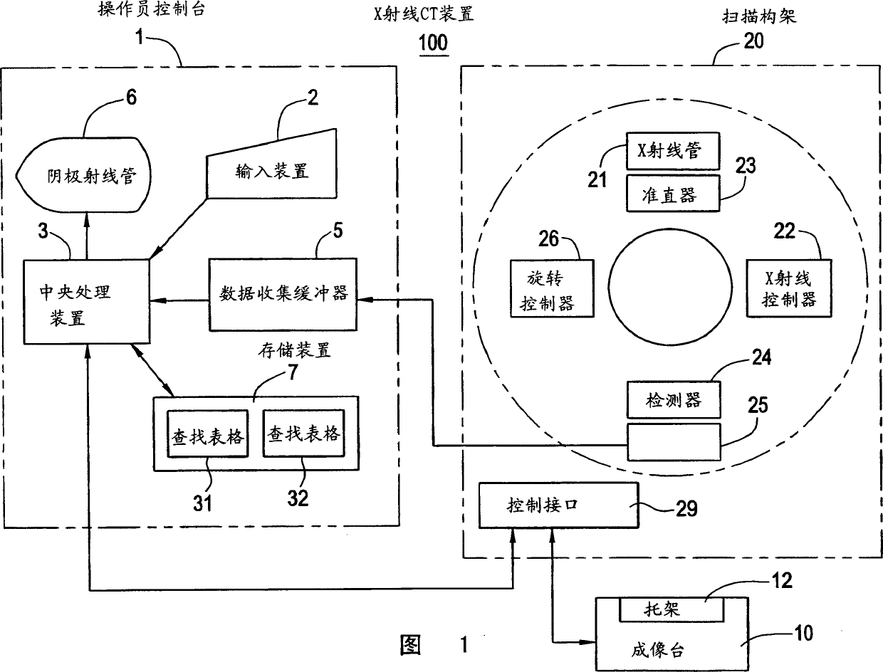
[0080] FIG. 1 is a block diagram showing the structure of an X-ray CT (computerized tomography) apparatus according to a first embodiment of the present invention.
[0081] The X-ray CT apparatus 100 includes an operator console 1 , an imaging table 10 and a scanning frame 20 .
[0082] The operator console 1 comprises input means 2 for receiving input signals issued by the operator, central processing means 3 for implementing the back-projection process according to the invention, data for collecting projection data acquired at the scanning frame Acquisition buffer 5, cathode ray tube (CRT) 6 for displaying X-ray CT images reconstructed from projection data and storage means 7 for storing programs, data and X-ray CT images.
[0083] The imaging table assembly 10 includes a carriage 12 for placing thereon an object to be imaged and transporting the object into / out of the cavity (lumen portion) of the scanning frame 20 . Carriage 12 is driven by a motor connected to imaging ta...
no. 2 example
[0141] In the second embodiment, for the following observation angle ranges, that is, the observation angle range of -45°≤view<45° (or the observation angle range mainly including this range and also including its adjacent areas) and 135°≤view<225 The observation angle range of ° (or the observation angle range that mainly includes this range and also includes its adjacent area), and for the following observation angle range, that is, the observation angle range of 45°≤view<135° (or mainly includes this range and also includes Including the observation angle range of its adjacent area) and the observation angle range of 225°≤view<315° (or mainly including this range and also including the observation angle range of its adjacent area), the backprojected pixel data D2 in the above two cases The addition of is processed separately, and finally the sums obtained from these additions are re-added, thereby obtaining backprojection data D3(x, y).
[0142] 14 and 15 are flowcharts sho...
no. 3 example
[0172] While in the first and second embodiments, one axial projection data D1 is calculated by interpolation calculation from two projection data D0, in the third embodiment, it is calculated by interpolation calculation from three projection data D0 An axial projection data D1.
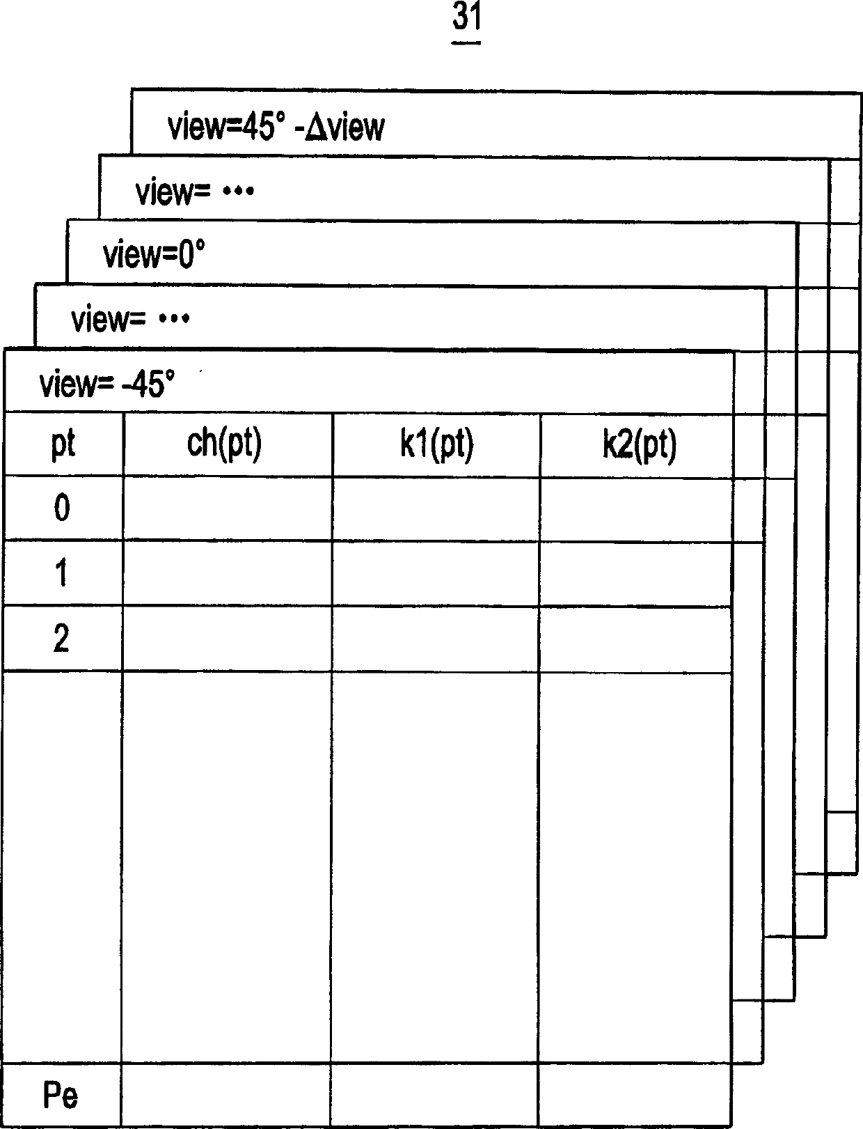
[0173] In this case, a look-up table 31' for axial projection as shown in FIG. 19 is used, and the axial projection data D1 is calculated according to the following equation:
[0174] D1 (view, pt) = k1 (pt) × D0 (view, ch (pt) + 2)
[0175] +k2(pt)×D0(view, ch(pt)+1)
[0176] +k3(pt)×D0(view, ch(pt)).
[0177] According to the X-ray CT apparatus of the third embodiment, back projection processing can be simplified and accelerated. Also, the accuracy has improved.
[0178] Some other examples
PUM
 Abstract
Description
Claims
Application Information