Supercharge Your Innovation With Domain-Expert AI Agents!

Method for fixation between electronic parts

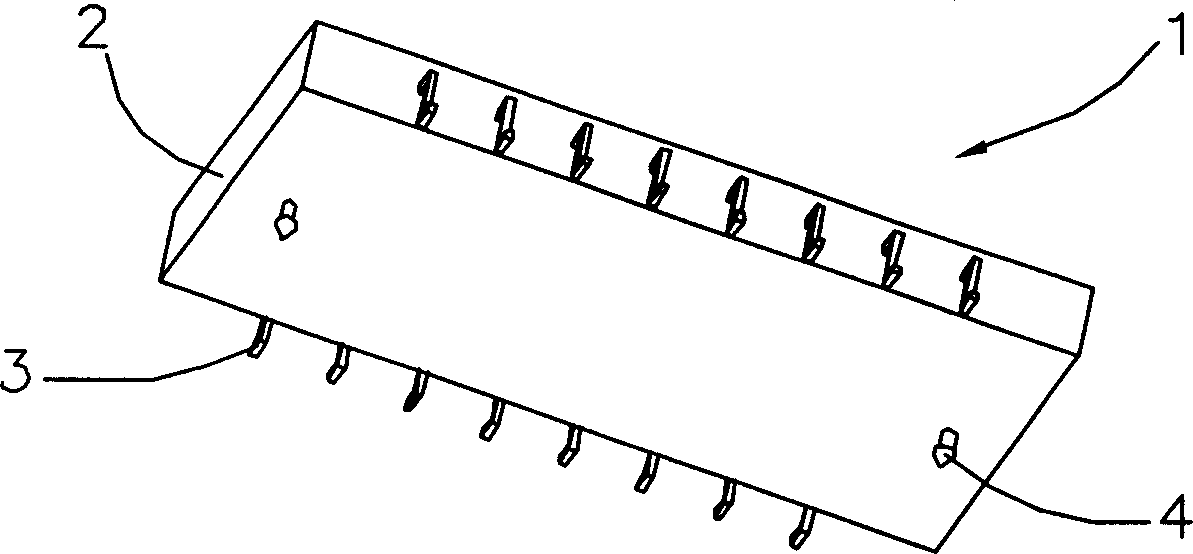
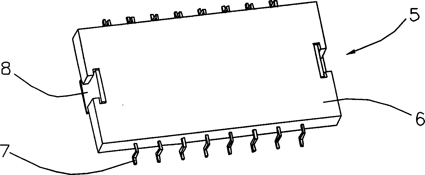
A technology for electronic parts and fixing methods, which is applied in the directions of printed circuit parts, structural connection of printed circuits, and assembling printed circuits with electrical components, which can solve the problem of poor contact between two electronic parts, insufficient fixing force, and difficulty between terminals 7 and metal The sheet body 8 is located on the same plane, etc., to achieve a good fixation effect and save fixation space.

Inactive Publication Date: 2003-10-01
DEYI PRECISION ELECTRONIC IND CO LTD PANYU
View PDF0 Cites 0 Cited by
  • Summary
  • Abstract
  • Description
  • Claims
  • Application Information

AI Technical Summary

Problems solved by technology

Although this fixing method saves a certain space, it brings another problem at the same time. The electronic parts are in poor contact (as shown in Figure 3), or the metal sheet body 8 is not welded to the docking electronic part 9, resulting in insufficient fixing force between the two electronic parts (as shown in Figure 4), and it is easy to fall off when subjected to vibration or impact

Method used


Image

  • Method for fixation between electronic parts
  • Method for fixation between electronic parts
  • Method for fixation between electronic parts

Examples


Embodiment Construction

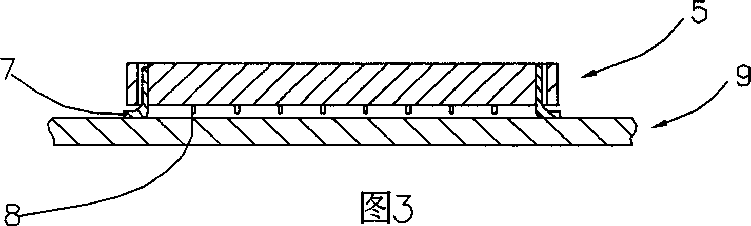
[0039] 5 and 6 show the first embodiment of the present invention, the first electronic component 10 includes a first body 12 and terminals 14 accommodated in the first body 12, and a surface of the first body 12 There are a plurality of grooves 16 that are roughly in the shape of an inverted trapezoid. The second electronic component 20 includes a second body 22 and solder paste 24 disposed on the body 22 . During assembly, the first electronic component 10 is placed on the second electronic component 20, and then heated at a high temperature. At about 185 degrees Celsius, the solder paste 24 gradually melts into liquid tin. Due to the effect of surface tension, the liquid tin will condense into an approximate spherical so as to enter the groove 16 of the first electronic component 10 . After cooling, the tin liquid will still partially remain in the groove 16, covering the lower edge of the groove 16 (as shown in FIG. 7 ), thereby fixing the first electronic component 10 on...


PUM


Abstract

A fixation method for electronic components includes the following steps: providing the first electronic component which has a number of containing spaces, setting a number of easily fusible assemblies corresponding to above-mentioned containing spaces on the second electronic component, placing the first one on the second one, heating above-mentioned two electronic components and to take them out after cooling off.

Description

technical field [0001] The invention relates to a fixing method between electronic parts, in particular to a fixing method for connecting two parts with a fusible component. Background technique [0002] At present, there are roughly two ways to fix electronic parts: through-hole and surface-mounted. Through-hole type such as figure 1 As shown, the electronic component 1 includes an insulating body 2 and a plurality of terminals 3 accommodated in the insulating body 2, and a pair of fastening posts 4 are extended downward from the insulating body 2 near its two ends for docking with The holes (not shown in the figure) of the electronic parts cooperate to achieve the purpose of fixing the two. However, this fixing method needs to be in contact with the two surfaces of the docking electronic parts, thus occupying a large space. Today, the electronic parts are becoming more and more miniaturized, especially when the docking electronic parts are multi-layer circuit boards. At...

Claims


Application Information

Patent Timeline
Patent Type & Authority Applications(China)
IPC IPC(8): H05K1/14H05K3/36
Inventor 朱德祥
Owner DEYI PRECISION ELECTRONIC IND CO LTD PANYU
Features
  • R&D
  • Intellectual Property
  • Life Sciences
  • Materials
  • Tech Scout
  • Unparalleled Data Quality
  • Higher Quality Content
  • 60% Fewer Hallucinations
Learn More