Check patentability & draft patents in minutes with Patsnap Eureka AI!

Positive and negative button switch device

A switch and button technology, which is applied in the field of positive and negative push button switches, can solve the problems of increasing the number of parts and the number of assembly man-hours, and achieve the effect of reducing the number of parts, reducing the number of assembly man-hours, and improving operability

Inactive Publication Date: 2003-10-29
KASUGA DENKI
View PDF0 Cites 3 Cited by
  • Summary
  • Abstract
  • Description
  • Claims
  • Application Information

AI Technical Summary

Problems solved by technology

As shown in Fig. 14, after the interlock mechanism and the switch contact mechanism are assembled at the switch element 3, the switch element 3 is installed in the case 1 and the cover 2, so the number of parts and the number of assembly man-hours increase. The problem

Method used


Image

  • Positive and negative button switch device
  • Positive and negative button switch device
  • Positive and negative button switch device

Examples


Embodiment Construction

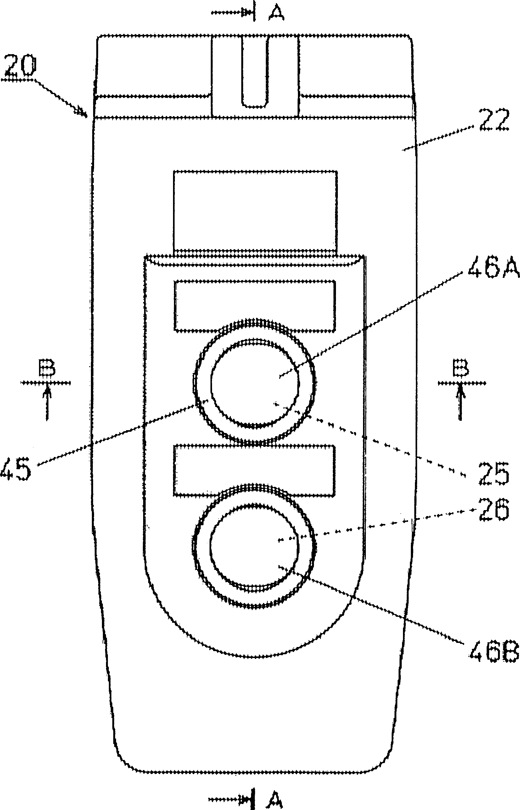
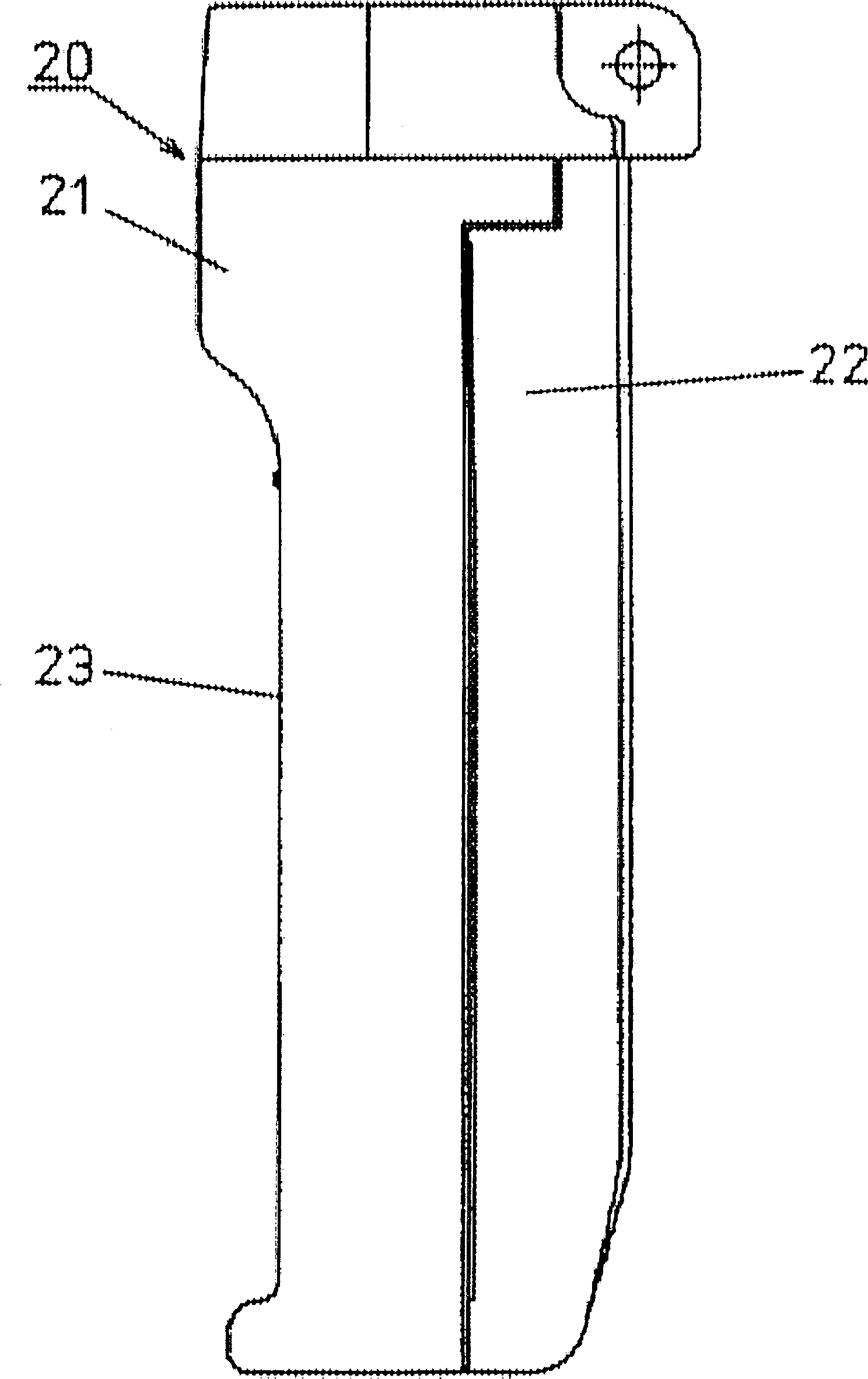
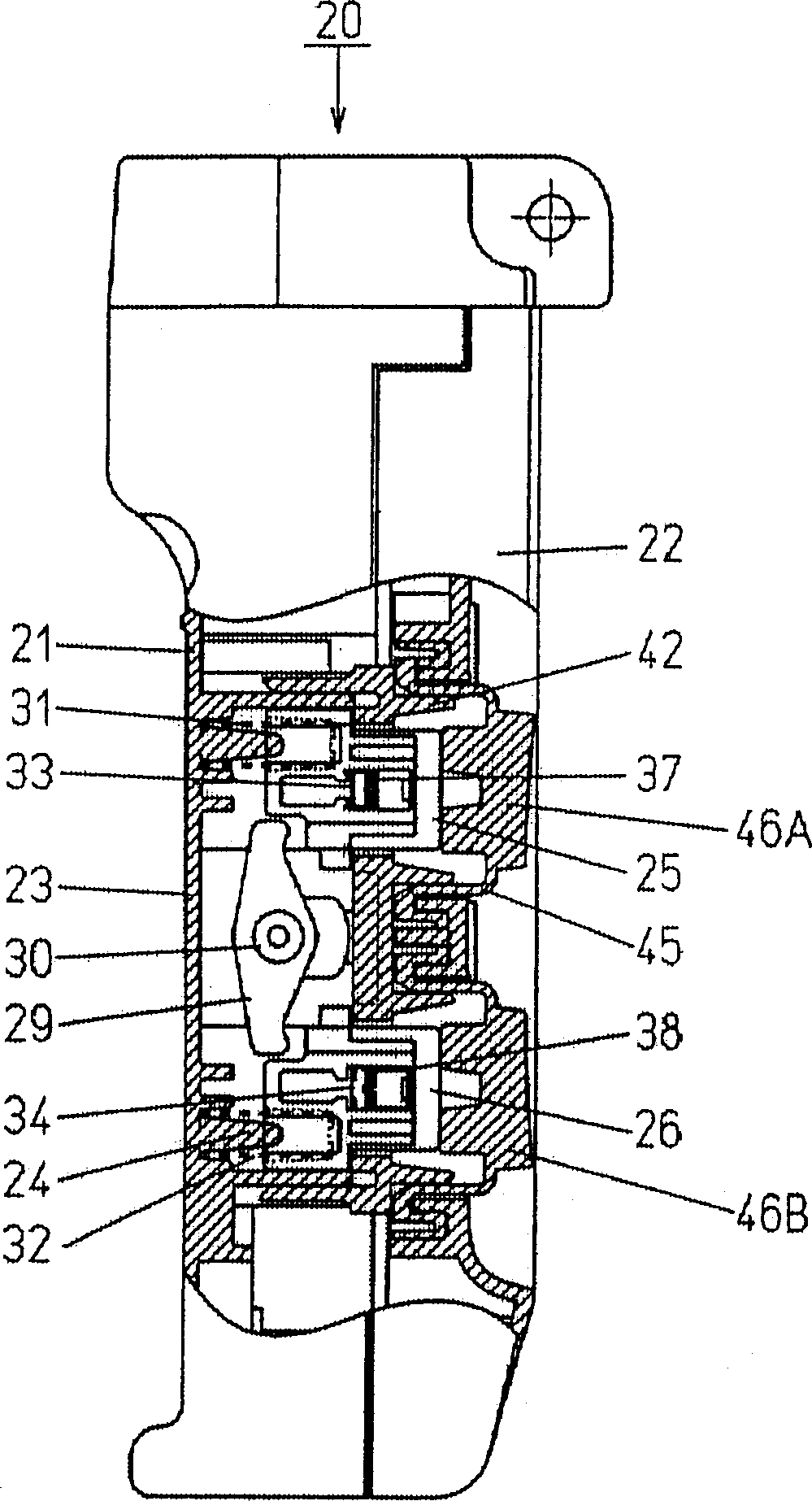
[0021] according to Figure 1~6 To illustrate, 20 is a positive and negative button switch, 21 is a housing with a concave portion 23 at the bottom, 22 is a cover, 24 is a base, and is integrally arranged on the inner bottom of the concave portion 23 with the housing 21, and 25 is a positive The button of turning, 26 is the button of reversing, and positive and negative button 25,26 are inserted in the insertion groove 27,27 of base 24, and 29 is interlocking plate, can return to at the bearing recess 28,28 places of base 24. The O-shaft portion 30,30 of the interlocking plate 29 is supported freely and freely, and the left and right sides of the interlocking plate 29 are positioned at the compression lower surfaces of the positive and negative buttons 25,26, so as to compress one of the two positive and negative buttons 25,26. An interlocking structure is provided so that another button cannot be pressed.

[0022] 31,32 are return springs, which are arranged in the insertion...


PUM


Abstract

The purpose of the invention is to realize the miniaturization of the handling portion of the press button and the operation improvement of the two-way press-button switcher, in which the component number and the assembling work are reduced to decrease the production cost. In the two-way press button on / off implement provided with a two-way press button, the on / off mechanism portion and the interlocking mechanism, a recessed portion is disposed on the bottom face of the housing of the on / off implement. The structure of the base station is constructed by disposing the base station through integrating the internal bottom portion of the housing in the upper recessed portion together with the housing so as to fix the movable body, which has the movable contact and is located opposite to the fixing contact of the base station, and the press button of the movable body on the pressing member having the protruding operation hole.

Description

technical field [0001] The invention relates to a forward and reverse pushbutton switch with an interlocking device used in the forward and reverse running control of cranes, winches and the like. Background technique [0002] Existing positive and negative button switches, such as Figure 11-1 As shown in 4, 1 is the shell, 2 is the cover, 3 is the switch element with an interlock mechanism, which is fixed in the shell 1, 4 and 4 are buttons, which are arranged on the switch element 3, and the button 4, 4 protrude from the housing 1, and the positive and negative switching action of the contact of the switch element 3 is performed by pressing the buttons 4, 4. In this structure, after assembling the interlock mechanism part and the switch contact mechanism part in the element case 5 and the element cover 6 of the switch element 3, they are fixed in the positive and negative push button switch case 1 and the cover 2. The structure of the switch element 3 therefore requires ...

Claims


Application Information

Patent Timeline
IPC IPC(8): H01H13/72H01H9/26H01H13/02H01H13/06H02B1/26H02B1/28
CPCH01H3/12H01H13/10H01H13/12
Inventor 森谷敏男
Owner KASUGA DENKI
Features
  • R&D
  • Intellectual Property
  • Life Sciences
  • Materials
  • Tech Scout
  • Unparalleled Data Quality
  • Higher Quality Content
  • 60% Fewer Hallucinations
Learn More