

Passenger conveyor
A technology for passenger transportation and steps, which is applied in the direction of transportation and packaging, escalators, etc., and can solve the problem of partial influence around the installation position of the turning space escalator
- Summary
- Abstract
- Description
- Claims
- Application Information
AI Technical Summary
Problems solved by technology
Method used
Image

Examples
Embodiment Construction
[0015] Below, will refer to Figure 1 to Figure 5 An escalator is shown to describe an embodiment of the passenger conveying device of the present invention.
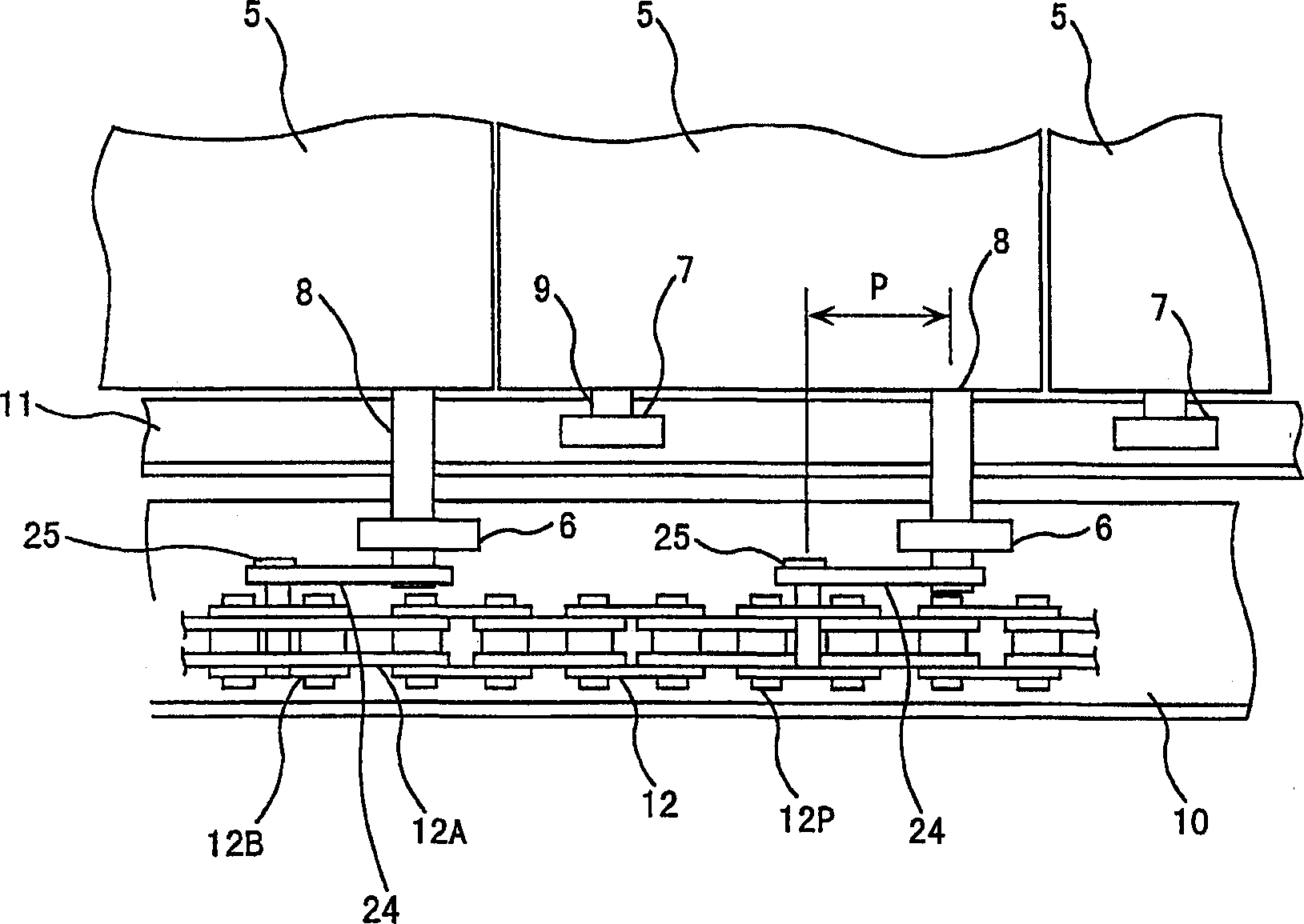
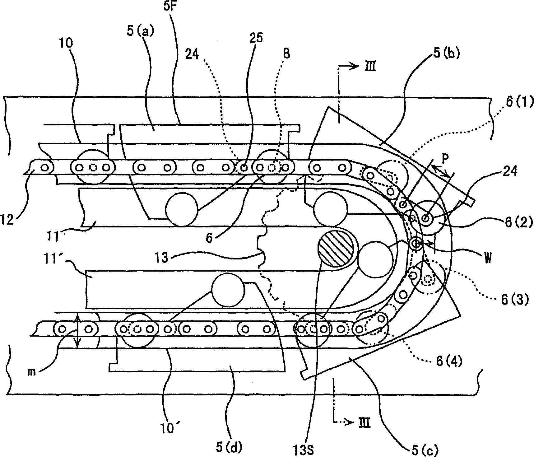
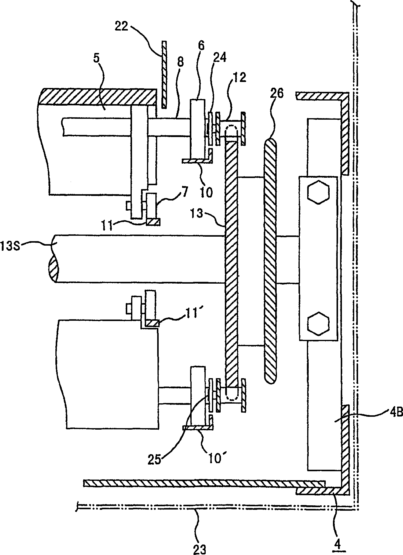
[0016] The escalator 1 of this invention is comprised as follows. That is, if Figure 4 As shown, a main frame 4 is installed between the upper floor 2 and the lower floor 3 which are vertically separated from each other, and in the main frame 4, a plurality of steps 5 moving along the longitudinal direction of the main frame are guided. The front wheels 6 are supported in both sides along the width direction of the upper step side of the step 5, and the rear wheels 7 are supported in both sides along the width direction of the lower step side, and the interval between the rear wheels is larger than the interval between the front wheels 6. small. Such as figure 1 As shown, the front wheel 6 and the rear wheel 7 are rotatably supported on the step 5 through the wheel shafts 8 and 9, respectively, and the two wheel sh...
PUM
 Abstract
Description
Claims
Application Information