
Optical recording medium

An optical recording medium, optical recording technology, applied in optical recording carrier, optical recording carrier manufacturing, recording/reproducing by optical method, etc.

Inactive Publication Date: 2003-11-12
SONY CORP
View PDF0 Cites 1 Cited by
  • Summary
  • Abstract
  • Description
  • Claims
  • Application Information

AI Technical Summary

Problems solved by technology

Currently no discs are known to have corrugations arranged for the needs of production processes such as control steps, injection molding steps and film forming steps

Method used


Image

  • Optical recording medium
  • Optical recording medium
  • Optical recording medium

Examples


no. 1 example

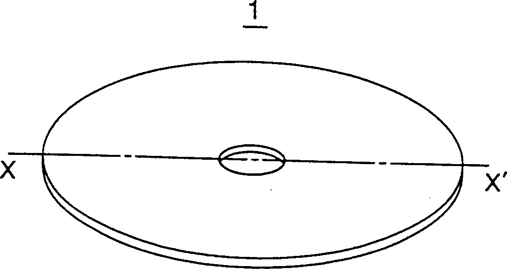
[0052] Fig. 2A is a perspective view of an optical disc according to this embodiment, and Fig. 2B is a sectional view taken along X-X' in Fig. 2A.

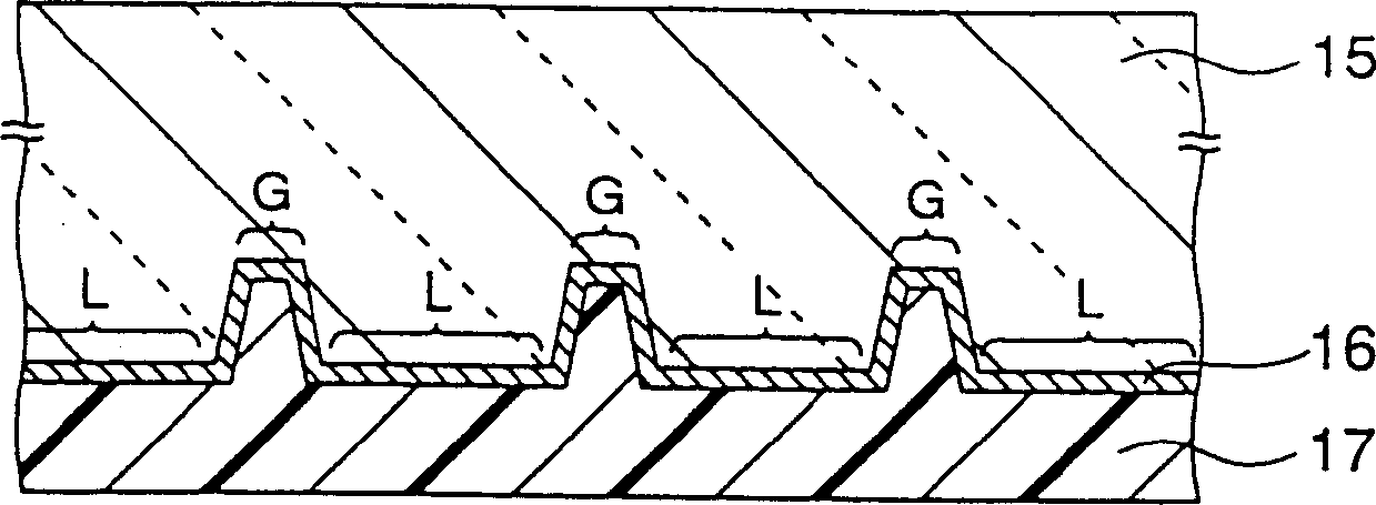
[0053] An optical disc 1 has a lamination of a disc substrate 15, an optical recording layer 16, and a protective layer 17, and has an approximately disc-shaped mold with an opening at its center.

[0054] Figure 3A is a diagram showing the Y corresponding to Figure 2B 1 A magnified view of a part of the cross-sectional structure and a schematic of the method of focusing light. In this figure, the right side is the inner circumferential side of the disc, and the left side is the outer circumferential side.

[0055] The chute surface 15a is provided on one surface of the disk substrate 15 having a thickness D1 of 1.1 to 1.2 mm. An optical recording layer 16 includes, for example, an insulating film, a recording film, another insulating film, and a reflective film, which are stacked in this order on the surface. The configuration...

no. 2 example

[0116] An optical disc of the present invention in the same manner as the first embodiment shown in FIG. 2 has a laminate of a disc substrate, an optical recording layer and a protective layer, and has an approximate disc shape with an opening portion at its center.

[0117] Fig. 9 is a plan view of the optical disc according to the present embodiment.

[0118] First chute surfaces 15a are alternately provided on one surface of a disk substrate 15 whose thickness is 1.1 to 1.2mm 1 And than the first chute surface 15a 1 Deeper second chute surface 15a 2 . On this surface is formed an optical recording layer in which, for example, an insulating film, a recording film, another insulating film and a reflection film are laminated in this order. The configuration of the film and the number of layers may vary depending on the type and design of the recording material.

[0119] A protective layer 17 is formed on the optical recording layer 16 .

[0120] On the optical disc as des...


PUM


Abstract

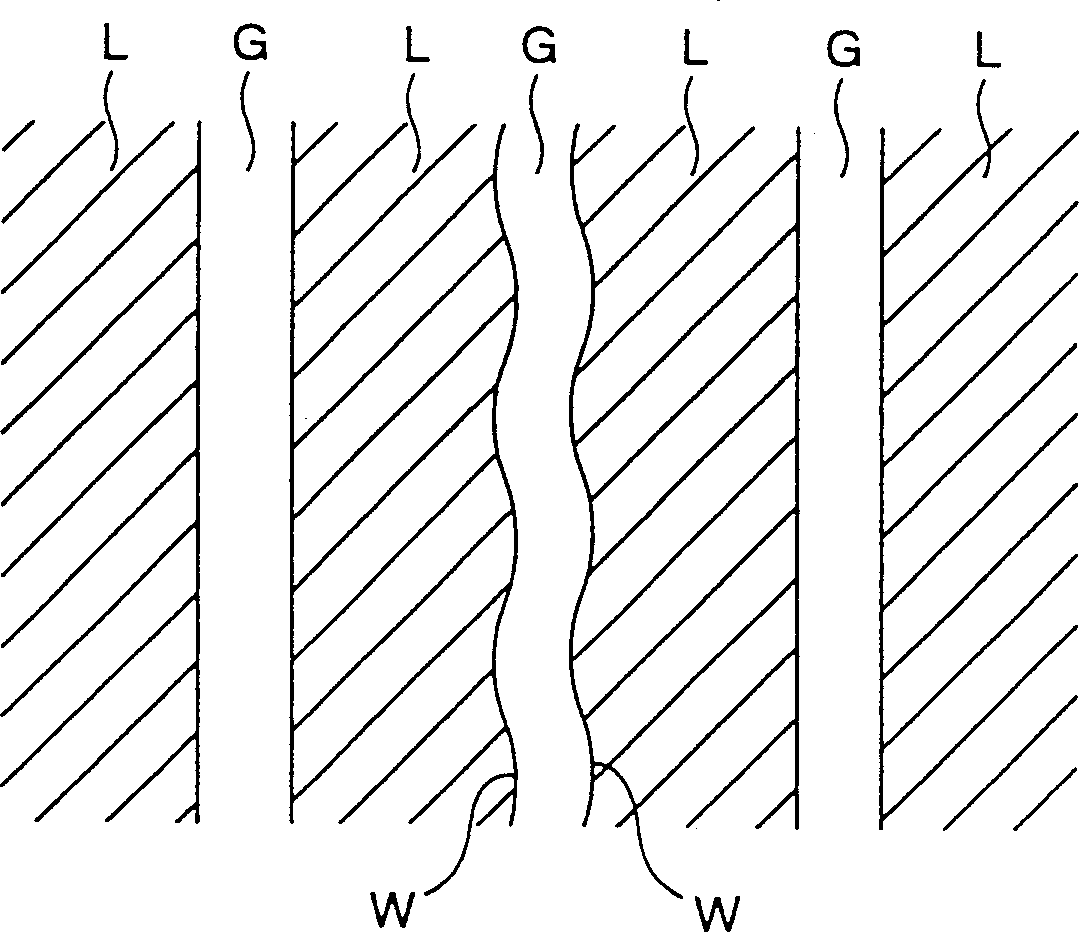
An optical recording medium having a wobble desirably arranged in a production process when having wobble at part of interfaces of lands and grooves is provided. An optical recording medium comprising an approximately disk-shaped disk substrate 15, formed in its surface with trenches 15a and having projections and recesses divided for every track region by the trenches 15a, on which are stacked an optical recording layer 16 having relief shapes corresponding with the trenches 15a and a protection film 17 and of a format where both regions of the projections (lands L) and the recesses (grooves G) are used as recording regions etc., wherein wobble W for providing clock information or address information is formed, between a pair of facing side walls forming each trench 15a, in a side wall portion at an inner circumferential side of the disk substrate 15 when seen from the recess (groove G) and at an outer circumferential side of the disk substrate 15 when seen from the projection (land L).

Description

technical field [0001] The present invention relates to an optical recording medium (hereinafter also referred to as "optical disk"), and more particularly to an optical recording medium capable of high-density recording. Background technique [0002] In recent years, with the development of technology for digitally recording moving pictures, still pictures and other video data, a large amount of data is processed, and CD or DVD and other optical disk devices are now the center of attention for large-capacity recording devices. It is still studying to further increase the capacity. [0003] Fig. 1 is a sectional view of a conventional optical disk. [0004] On one surface of a light transmission type disc substrate 15 having a thickness of approximately 1.2 mm, groove surfaces 15a are provided. On this surface is formed an optical recording layer 16 in which, for example, an insulating film, a recording film, another insulating film, a reflective film, etc. are stacked in ...

Claims


Application Information

Patent Timeline
Patent Type & Authority Applications(China)
IPC IPC(8): G11B7/00G11B7/007G11B7/24079G11B7/24082G11B7/26G11B27/19G11B27/24
CPCG11B7/263G11B7/007G11B2220/2529G11B7/261G11B27/24G11B2220/20G11B27/19G11B7/00G11B2007/00754
Inventor 藤田五郎坂本哲洋
Owner SONY CORP
Learn More