Supercharge Your Innovation With Domain-Expert AI Agents!

Deflection yoke with vertical deflection coil fixing structure

A deflecting device and vertical deflection technology, applied in the field of deflecting devices and hook-like protrusions, can solve problems such as poor user health, poor user, and incorrect landing of electron beams

Inactive Publication Date: 2004-03-24
SAMSUNG ELECTRO MECHANICS CO LTD
View PDF2 Cites 0 Cited by
  • Summary
  • Abstract
  • Description
  • Claims
  • Application Information

AI Technical Summary

Problems solved by technology

[0031] The quality of the TV picture was deteriorated due to the mis-landing of the electron beam emitted from the electron gun due to the poor fixing state of the vertical deflection coil 3
[0032] Also, a bad smell is generated from the hot-melt material in the process of applying the hot-melt material to the vertical deflection yoke 3, and the smell has a bad effect on the user's health, and the user can feel it due to the bad smell Uncomfortable, which creates a bad work environment

Method used


Image

  • Deflection yoke with vertical deflection coil fixing structure
  • Deflection yoke with vertical deflection coil fixing structure
  • Deflection yoke with vertical deflection coil fixing structure

Examples


Embodiment Construction

[0059] Preferred embodiments of the present invention will now be described in detail with reference to the accompanying drawings, wherein like numerals are used for like parts throughout. The embodiments described below are intended to illustrate the present invention with reference to the drawings.

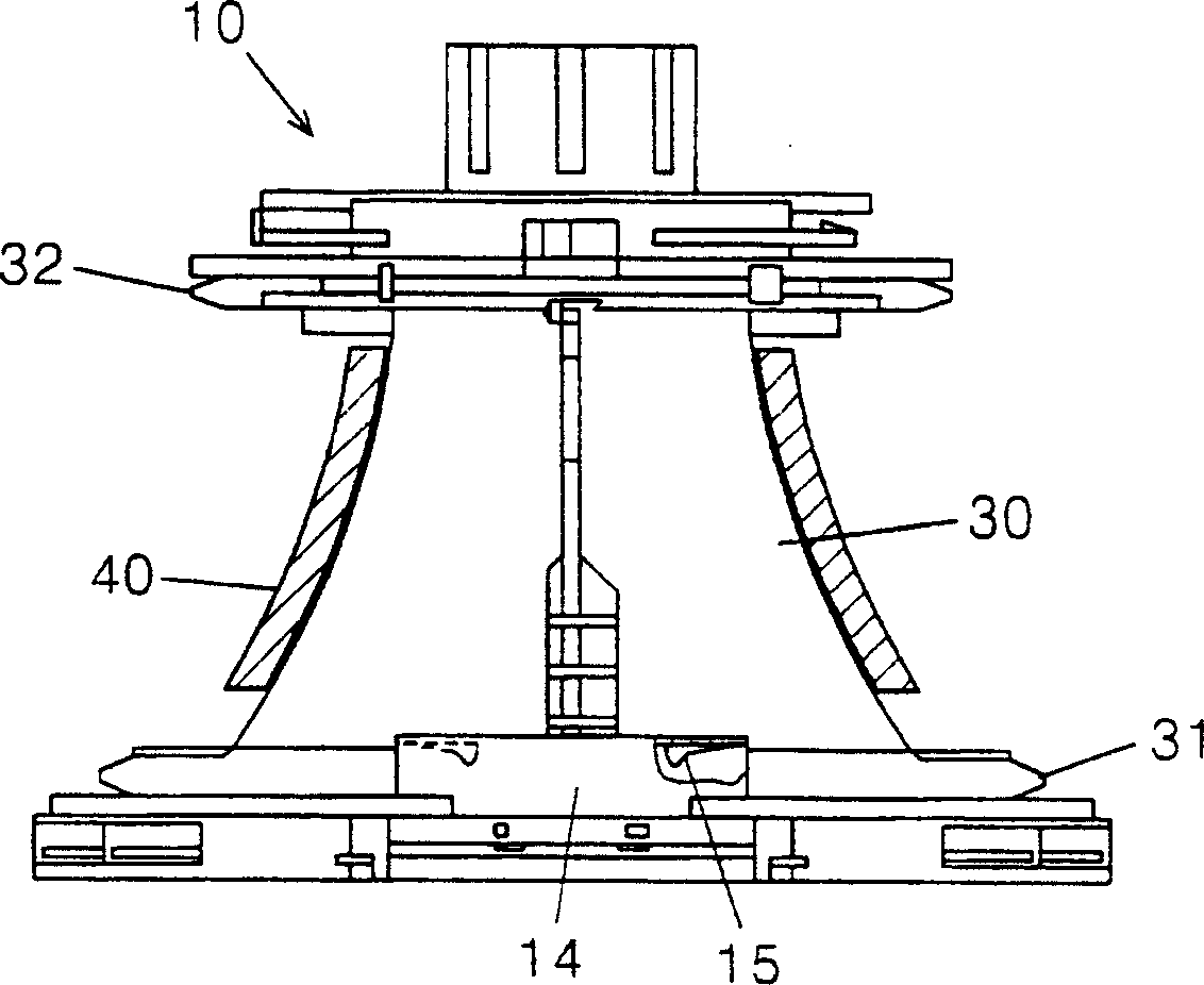
[0060] image 3 A view showing a vertical deflection coil fixing structure of a deflection device according to an embodiment of the present invention, Figure 4 show image 3 A view of the coil splitter of the deflection unit shown in, Figure 5 shows along the Figure 4 A view of the A-A line, and Figure 6 shows along the Figure 5 View of the B-B line.

[0061] refer to image 3 , the deflection device includes a coil splitter 10, a horizontal deflection coil (not shown) and a vertical deflection coil 30, positioned inside and outside the coil splitter 10, to deflect the electron beam emitted from the electron gun in the horizontal and vertical directions, respectively, ...


PUM


Abstract

A deflection yoke includes a coil separator having a screen portion, a neck portion, and a connection portion, and having at least one protrusion formed on at least one of the screen portion and the neck portion, a horizontal deflection coil disposed on an inside of the coil separator to generate a horizontal magnetic field, a vertical deflection disposed on an outside of the coil separator to generate a vertical magnetic field, and having a pin hole formed on a position corresponding to the at least one protrusion coupling the vertical deflection coil to the coil separator.

Description

[0001] Cross References to Related Applications [0002] This application claims priority from Korean Patent Application No. 2002-43002 filed in 2002 with the Korean Intellectual Property Office and Korean Patent Application No. 2003-37122 filed in 2003, and the contents thereof are hereby cross-referenced. technical field [0003] The present invention relates to CRTs mounted on computer monitors or TV monitors, and more particularly to deflection units having hook-like protrusions formed on coil separators for easy mounting of vertical deflection coils on the coil separators, thereby eliminating application of thermal melt process (hot-meltapplying process) to improve installation and production efficiency, the deflection coil having the assembly protrusion formed on the coil separator is inserted into the assembly groove formed on the divided surface of each core to provide vertical deflection Coil assembly reliability. Background technique [0004] Generally, a cathode ...

Claims


Application Information

Patent Timeline
Patent Type & Authority Applications(China)
IPC IPC(8): H01J29/76
CPCH01J29/76
Inventor 崔焕奭金圣云
Owner SAMSUNG ELECTRO MECHANICS CO LTD
Features
  • R&D
  • Intellectual Property
  • Life Sciences
  • Materials
  • Tech Scout
  • Unparalleled Data Quality
  • Higher Quality Content
  • 60% Fewer Hallucinations
Learn More