Vertical deflection extension end member

Active Publication Date: 2010-11-25
TSF SYST
View PDF99 Cites 15 Cited by
  • Summary
  • Abstract
  • Description
  • Claims
  • Application Information

AI Technical Summary

Benefits of technology

[0011]The wall structure discussed herein may have an infinite vertical range of movement because the vertical stud has a telescoping portion and a stationary portion which are nested within each other to permit infinite spatial variations between the top track attached to the ceiling and the bottom track attached to the floor without crushing or pulling apart the metallic vertical studs. The wall structure allows for ceiling to floor variations during (1) settling of the building, (2) seismic shifts and (3) expansions and contractions due to ambient temperature changes and fire. Additionally, the wall structure prevents detachment of the drywall from the wall frame (Le., vertical studs, top and bottom tracks) due to the different thermal expansion rates of the drywall and the metallic wall frame when the wall is subjected to heat (e.g., fire).
[0012]To this end, the drywall is attached to only the stationary portion of the vertical stud and not to the telescoping portion and the top track. By way of example and not limitation, the stationary portion of the vertical stud may be attached to the bottom track. The stationary portion of the vertical stud may have a C-shaped configuration which circumscribes the telescoping portion. The telescoping portion may be pushed deeper into the stationary portion or pulled out of the stationary portion. In attaching the drywall to the stationary portion but not the telescoping portion, sidewalls of the

Problems solved by technology

The reason is that the screws used to attach the drywall to the stationary portio

Method used


Image

  • Vertical deflection extension end member
  • Vertical deflection extension end member
  • Vertical deflection extension end member

Examples


Embodiment Construction

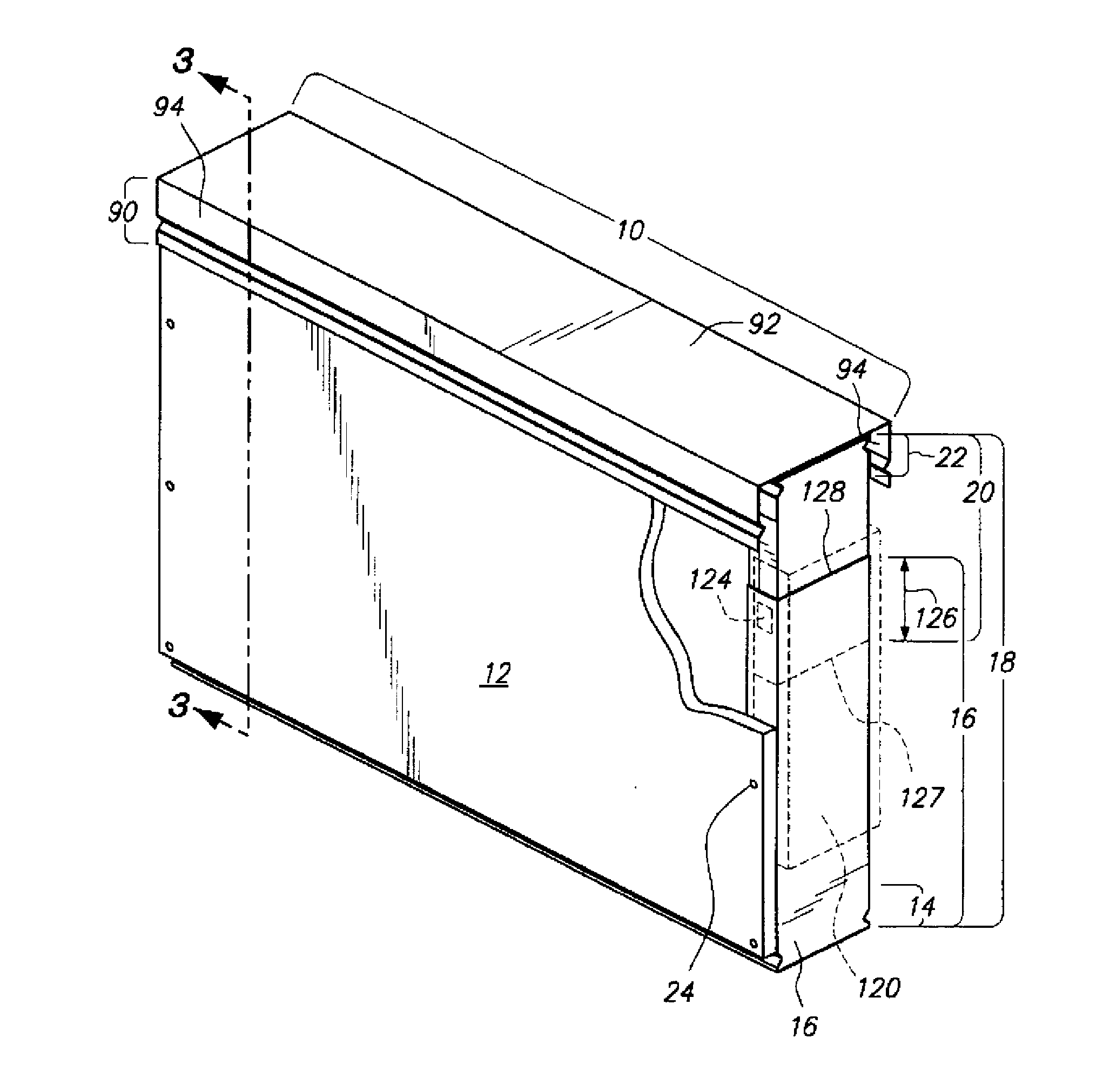
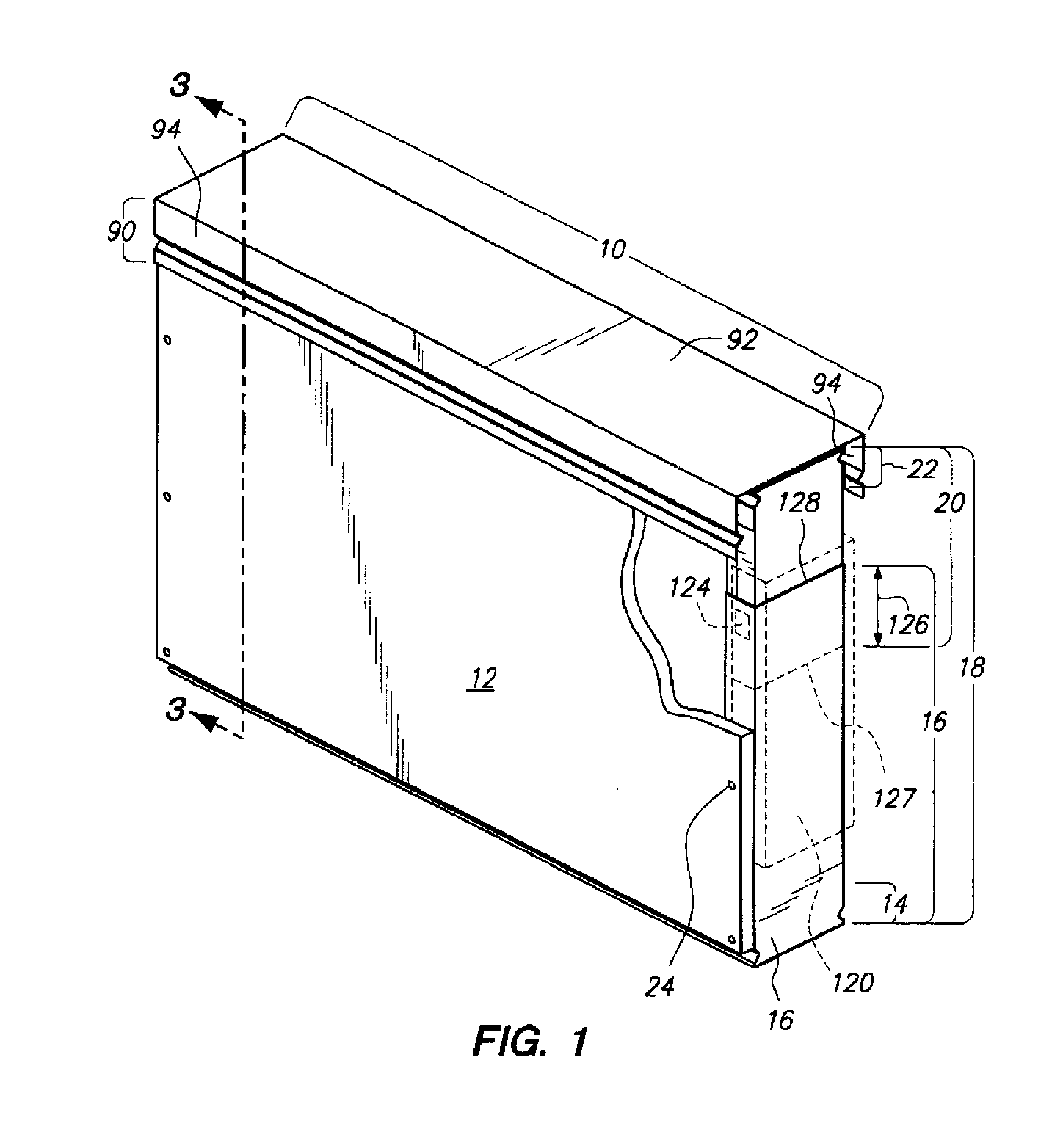
[0024]Referring now to FIG. 1, a wall structure 10 is shown. Drywall 12 is secured to stationary portions 16 of vertical studs 18 and not to telescoping portions 20 of the vertical studs 18. A top track 22 is attached to the telescoping portion 20 but not the drywall 12. When ceiling to floor variations occur such as during a fire, ambient temperature changes, settling of the building, earthquakes (i.e., seismic shifts, etc.), the telescoping portions 20 of the vertical studs 18 allow for variation in the ceiling to floor distance. Additionally, such construction would also mitigate detachment of the fasteners 24 from the drywall 12 due to different coefficients of thermal expansion of the drywall 12 and the material (e.g., steel) from which the vertical stud 18 is fabricated during ambient temperature changes or fire.

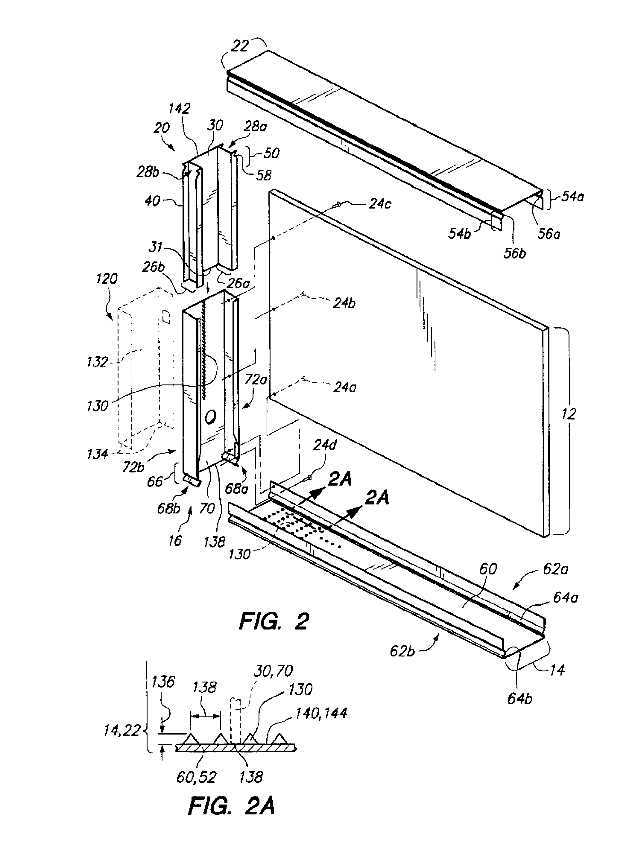
[0025]As shown in FIG. 2, in order to fasten the drywall 12 to the stationary portion 16 but not the telescoping portion 20, one or both sidewalls 26a, b of the telesc...


PUM


Abstract

A wall structure has a telescoping portion and a stationary portion. An overlapping section of the telescoping portion has a recess to allow dry wall to be fastened to the stationary portion at the overlapping section without being attached to the telescoping portion. The fastener pierces through the drywall and a sidewall of the stationary portion. However, a tip of the fastener does not engage a sidewall of the telescoping portion. Rather, the tip of the fastener stops within the recess of the telescoping portion.

Description

CROSS-REFERENCE TO RELATED APPLICATIONS[0001]Not ApplicableSTATEMENT RE: FEDERALLY SPONSORED RESEARCH / DEVELOPMENT[0002]Not ApplicableBACKGROUND[0003]The present invention relates to wall structures that may be fire rated and / or accommodate seismic shifts or settlings of the building.[0004]In building construction, conventional wall fabrication techniques employ wooden materials such as headers and footers as well as wooden vertical studs placed between the headers and footers to form a wall frame. Unfortunately, traditional wooden wall constructions suffer from several drawbacks including the excessive time to erect the wall structure, high material costs, and heavy weight.[0005]In certain situations, metallic framing structures are now used in buildings due to its light weight, ease of erecting the wall structure and low expense. Nonetheless, these metallic wall frames suffer from other deficiencies. In particular, the metallic framing structures are fabricated similar to a wooden ...

Claims


Application Information

Patent Timeline
IPC IPC(8): E04B2/08E04C2/38E04G25/06
CPCE04B2/7457E04B2/767E04B2/82E04B2/789E04B2/7854E04B2/7459
Inventor ANDREWS, WILLIAM
Owner TSF SYST
Why Eureka
Try Eureka