Pivoting platform having a piezoelectric drive

a piezoelectric drive and platform technology, applied in the field of pivoting platforms, can solve the problems of inefficient operation and undue stress on the mirror

Inactive Publication Date: 2005-10-18
TEXAS INSTR INC
View PDF4 Cites 15 Cited by
  • Summary
  • Abstract
  • Description
  • Claims
  • Application Information

AI Technical Summary

Problems solved by technology

If a magnetic drive were utilized which requires the mounting of a permanent magnet on the mirror, the mass of the permanent magnet would be larger than the mass of the mirror, which would place undue stresses on the mirror and make for an inefficient operation.

Method used


Image

  • Pivoting platform having a piezoelectric drive
  • Pivoting platform having a piezoelectric drive
  • Pivoting platform having a piezoelectric drive

Examples


Embodiment Construction

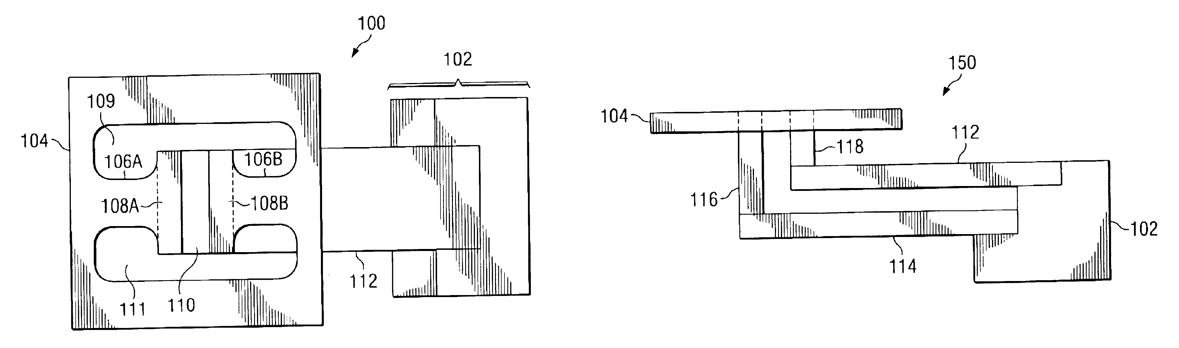
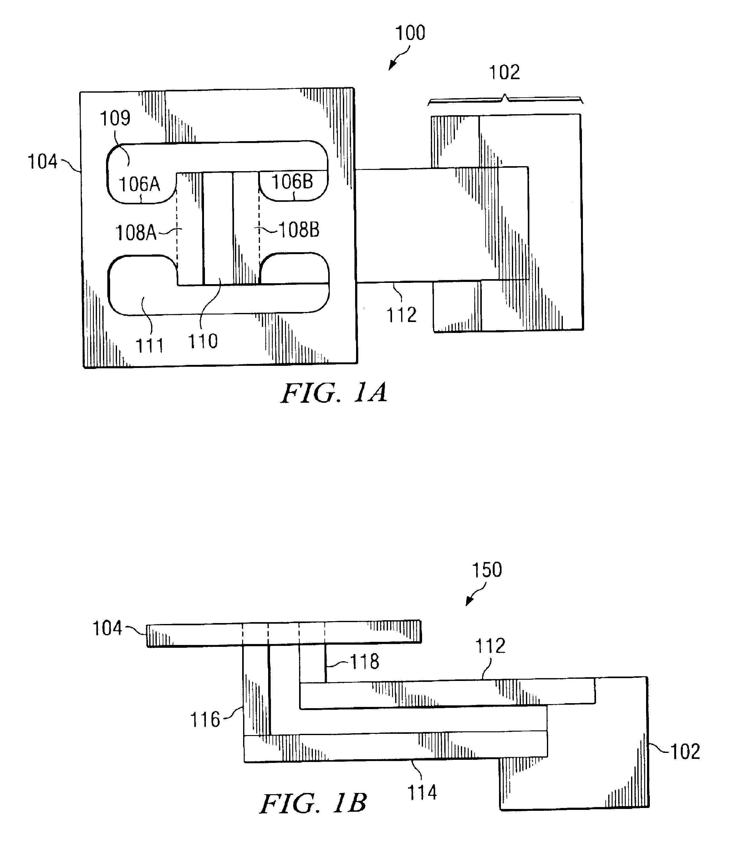
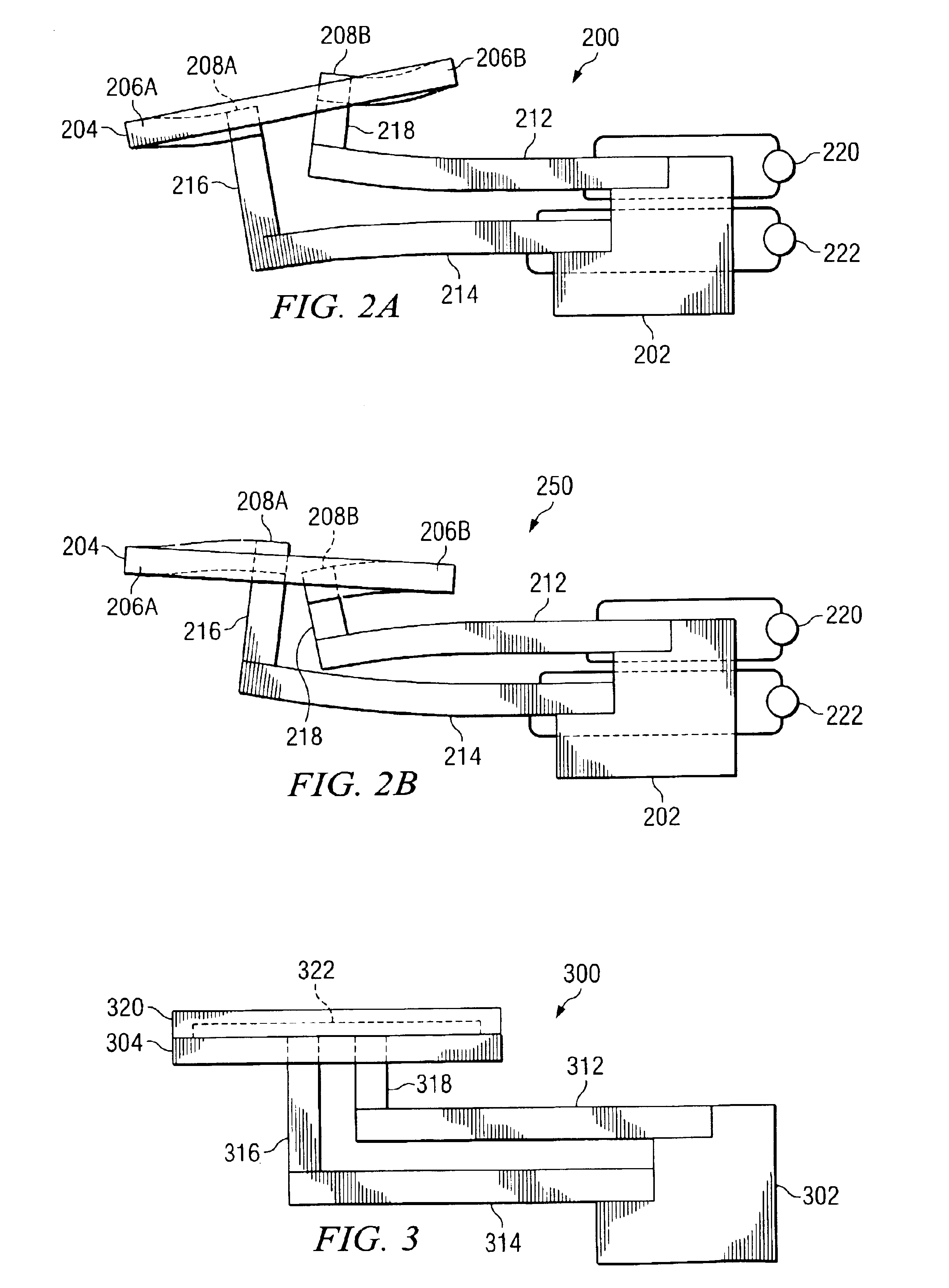
[0014]Referring to FIG. 1A, a plan view of the present invention is shown generally as 100. A support 102 has attached thereto two piezoelectric elements 112 and 114 (element 114 is not shown in FIG. 1A) in which the element 112 is above element 114. Referring to FIG. 1B, a side view of FIG. 1A is shown generally as 150. In the side view, it can be seen that element 112 and element 114 are physically located one above the other and are attached to the support at stepped portions of the support. Each of the elements 112, 114 can be the same length, but this is not required. The piezoelectric elements 112, 114 are made from a piezoelectric material known in art, which is a two-layer element that produces a curvature when one layer expands while the other layer contracts. These devices, sometimes referred to as “benders”, produce this curvature when an appropriate electric voltage is applied thereto. Piezoceramic elements possessing these properties are available through Piezo Systems ...


PUM


Abstract

A pivoted platform has two flexible arms having rigid end zones which are attached by means of spacers to piezoelectric elements. The piezoelectric elements are made to deflect in opposite directions upon the application of the electrical signal to cause the platform to pivot. Applying voltages of the opposite polarity causes the platform to pivot in the opposite direction. A mirror may be attached to the platform to produce a scanning mirror for the vertical deflection of a television image.

Description

REFERENCE TO RELATED APPLICATIONS[0001]This application is related to U.S. patent application Ser. No. 10 / 458,995 entitled “Position Sensor For A Pivoting Platform”, commonly assigned and filed on even date herewith, which is incorporated herein by reference.FIELD OF THE INVENTION[0002]This application relates to a pivoting platform and more particularly to a pivoting platform for a scanning micromirror device.BACKGROUND OF THE INVENTION[0003]Micromirror devices for use, for example, in optical communications techniques and for optical matrix switches are known in the art. For example, apparatus useful for such communications links is known from U.S. Pat. No. 6,295,154, entitled “Optical Switching Apparatus”, commonly assigned herewith and incorporated herein by reference. This patent discloses a micromirror assembly for directing a light beam in an optical switching apparatus. As disclosed in this patent, which reflects the light beam in a manner that may be precisely controlled by...

Claims


Application Information

Patent Timeline
Patent Type & Authority Patents(United States)
IPC IPC(8): G02B7/182
CPCG02B7/1821Y10S359/90
Inventor HEATON, MARK W.TURNER, ARTHUR M.
Owner TEXAS INSTR INC
Why Eureka
Try Eureka