Headlight devices for vehicles and optic axis position setting method

A setting method and technology of headlights, applied in the direction of headlights, signaling devices, vehicle parts, etc., can solve problems such as unsatisfactory, complicated and large-scale problems, and achieve the effect of ensuring proper control

Inactive Publication Date: 2004-04-21
KOITO MFG CO LTD
View PDF1 Cites 4 Cited by
  • Summary
  • Abstract
  • Description
  • Claims
  • Application Information

AI Technical Summary

Problems solved by technology

[0005] However, installing such a potentiometer is not ideal because it will lead to a complication and enlargement of the structure of the actuator.

Method used


Image

  • Headlight devices for vehicles and optic axis position setting method
  • Headlight devices for vehicles and optic axis position setting method
  • Headlight devices for vehicles and optic axis position setting method

Examples


Embodiment Construction

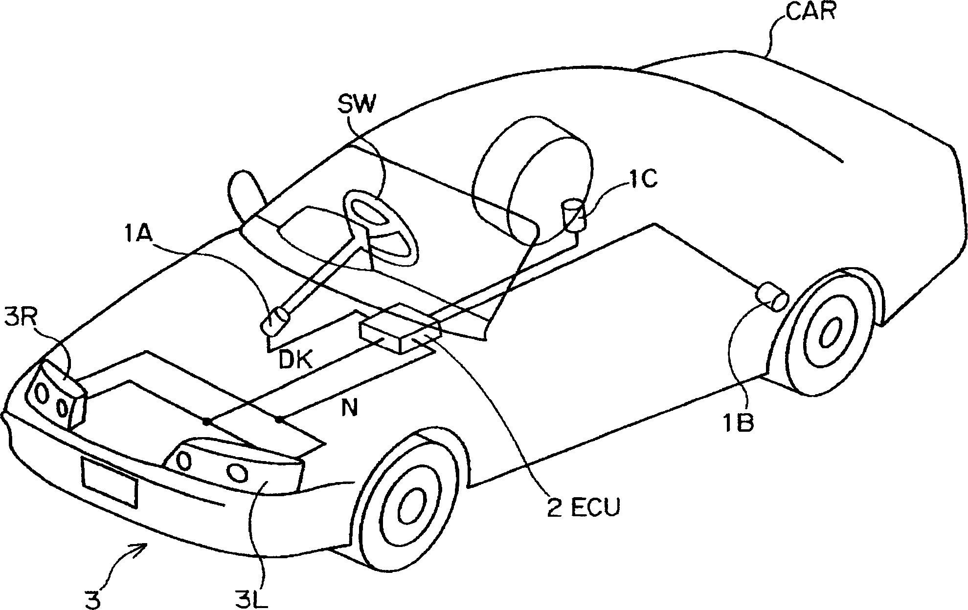
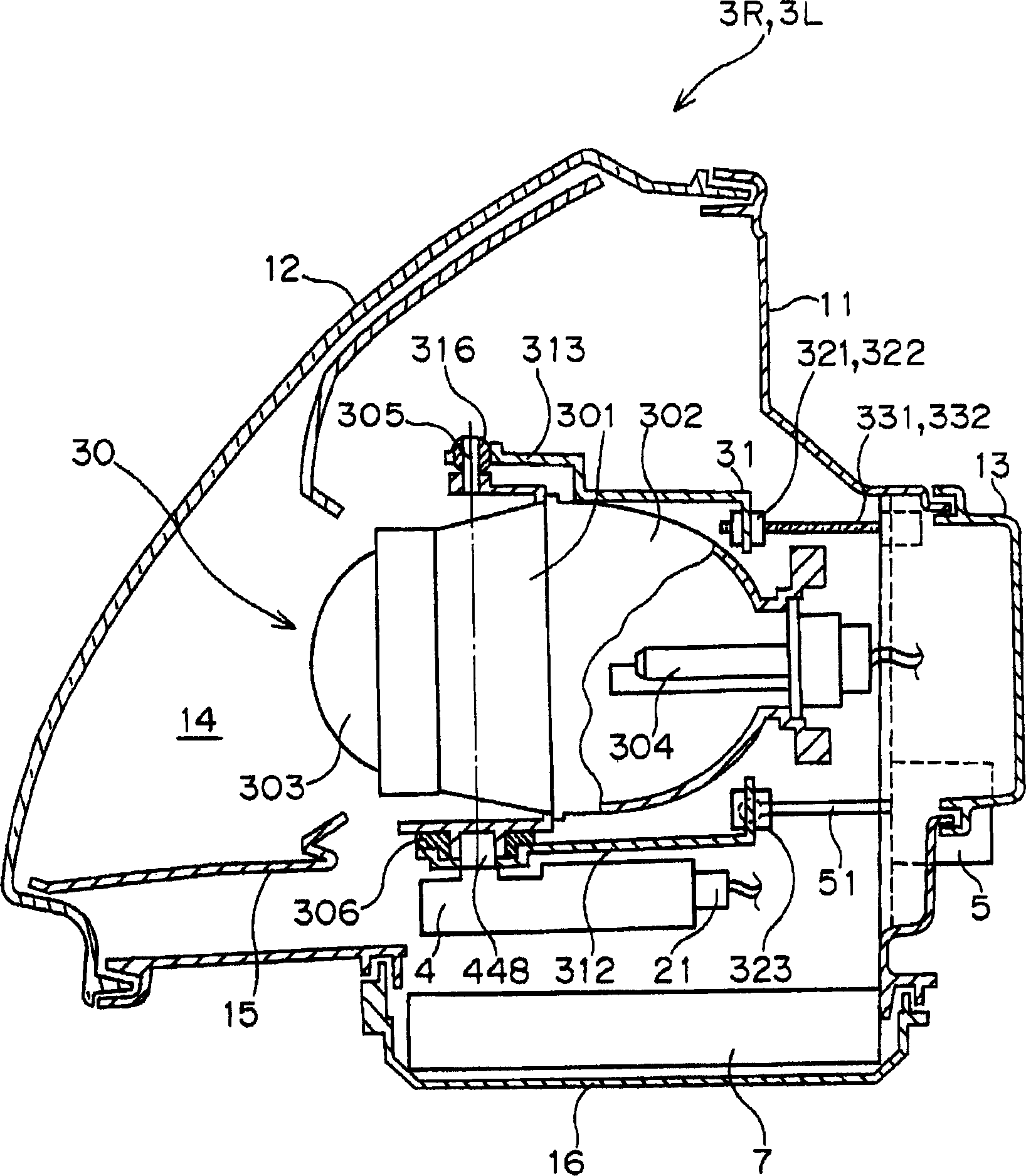
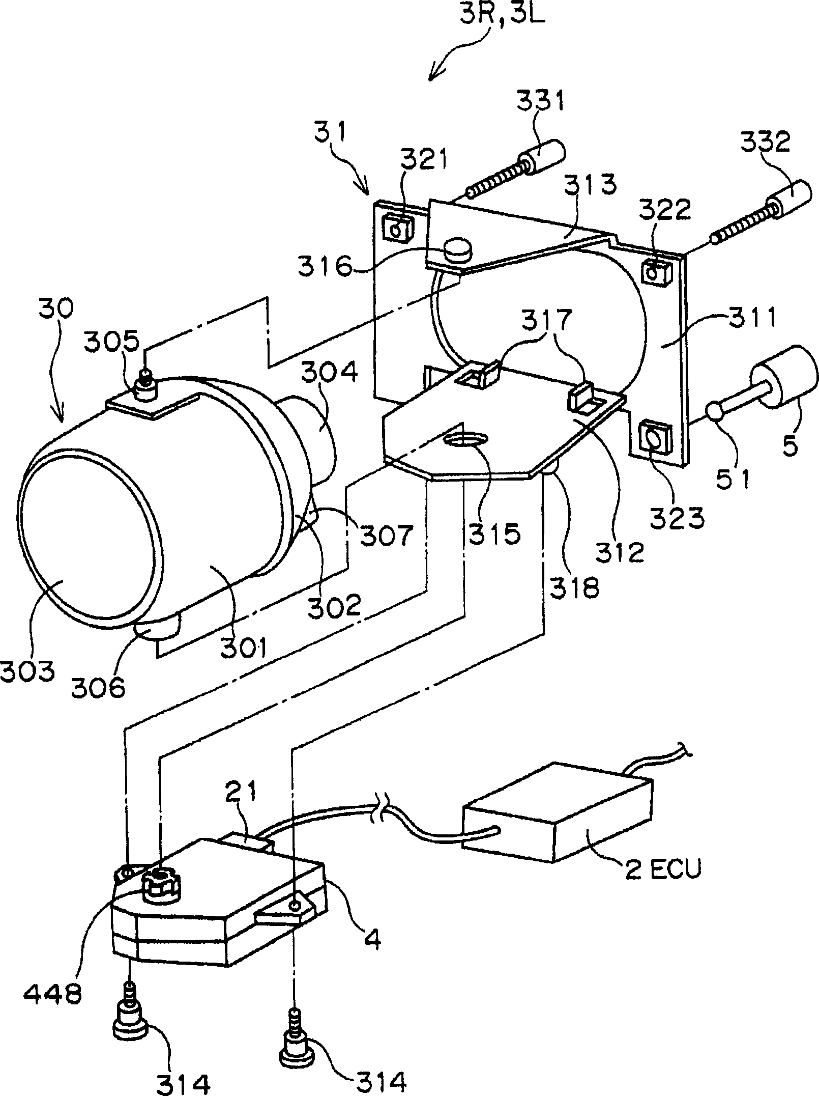
[0025] Embodiments of the present invention will be described below with reference to the drawings. figure 2 yes figure 1 A vertical cross-sectional view of the internal structure of a headlamp composed of a turn signal that can deflect the irradiation direction left and right among the AFS structural elements shown as the lamp deflection angle control device of the present invention, image 3 is a partially exploded three-dimensional view of its main parts. The lens 12 is opened at the front of the lamp body 11 , and the rear cover 13 is mounted on the rear opening to form a lamp chamber 14 , and a projection lamp 30 is disposed in the lamp chamber 14 . Since the projection lamp 30 is widely used in which the body housing 301, reflector 302, lens 303 and light source 304 are integrated, detailed description is omitted here, but the light source 304 used here is a discharge bulb. The projection lamp 30 is supported by a substantially U-shaped bracket 31 . A protruding port...


PUM


Abstract

A headlamp apparatus for a vehicle includes a left-right deflecting device for deflecting an optical axis of illumination of a projector lamp in a left-and-right direction in correspondence with a steering angle of a vehicle; a vertically deflecting device for deflecting the optical axis of illumination of the projector lamp 30 in a vertical direction; and a deflection controlling device for effecting the operation of setting the optical axis by the left-right deflecting device at a time when the optical axis of illumination is in a state of being oriented in a lower direction than the horizontal direction by the vertically deflecting device. The optical axis position of the projector lamp is oriented in a lower direction than the horizontal direction by the vertically deflecting device until the optical axis position is set to a reference angular position by the left-right deflecting device.

Description

technical field [0001] The present invention relates to a vehicle headlamp device such as an automobile, and more particularly to a light distribution control device equipped with a light distribution control device that makes the irradiation direction and the irradiation range of the headlamp track and change according to the driving conditions, such as an adaptive lighting system (hereinafter referred to as AFS (Adaptive Front- A vehicle headlamp device capable of setting the optical axis of the headlamp at a reference angular position with high precision in a headlamp device of a Lighting System adaptive headlamp lighting system) and a method for setting the optical axis position thereof. Background technique [0002] As an AFS proposed for improving the driving safety of automobiles, its technology is disclosed in Japanese Unexamined Patent Application Publication No. 2002-160581 proposed by the present applicant. The AFS as figure 1 As shown in the conceptual diagram o...

Claims


Application Information

Patent Timeline
Patent Type & Authority Applications(China)
IPC IPC(8): B60Q1/06B60Q1/076B60Q1/10B60Q1/12
CPCB60Q1/12B60Q2200/38B60Q1/10B60Q1/06
Inventor 滝井直树草谷雅弘杉本笃马场淳治
Owner KOITO MFG CO LTD
Why Eureka
Try Eureka